Lever-type connector and connector assembly

a technology of lever-type connectors and connector assemblies, which is applied in the direction of coupling device connections, coupling parts engagement/disengagement, and incorrect coupling prevention, etc., can solve the problems of insufficient contact margins between terminal fittings accommodated in the two housings, and achieve the effect of reducing the size of the lever and being sufficiently strong

Active Publication Date: 2009-07-02
SUMITOMO WIRING SYST LTD
View PDF9 Cites 9 Cited by
  • Summary
  • Abstract
  • Description
  • Claims
  • Application Information

AI Technical Summary

Benefits of technology

[0009]The exertion of forces on the two supports assures that first housing is prevented from becoming oblique and assures that sufficient contact margins are assured between the terminal fittings in the two housings. Further, the first and second modes can be selected depending on the support on which the lever is mounted. Thus, the lever can be remounted to improve versatility. Further, the construction of the first housing can be simplified as compared with the case where a special engageable portion engageable with the second part is provided to prevent the housings from becoming oblique.
[0013]The first part preferably is a cam groove and the second housing preferably has a plurality of follower pins located at positions substantially corresponding to the respective first and second modes for engaging the first part. The lever preferably has an escaping groove for receiving the follower pin that is not engaged with the first part. The entry of the follower pin into the escaping groove avoids interference between the lever and the follower pin. The escaping groove does not reduce the size of the lever significantly, and hence the lever is sufficiently strong.

Problems solved by technology

Thus, the first housing may be distanced from a connecting surface of the second housing at the second longitudinal side when the connecting operation of the two housings is completed and contact margins between terminal fittings accommodated in the two housings may be insufficient at the second longitudinal side.

Method used


Image

  • Lever-type connector and connector assembly
  • Lever-type connector and connector assembly
  • Lever-type connector and connector assembly

Examples


Embodiment Construction

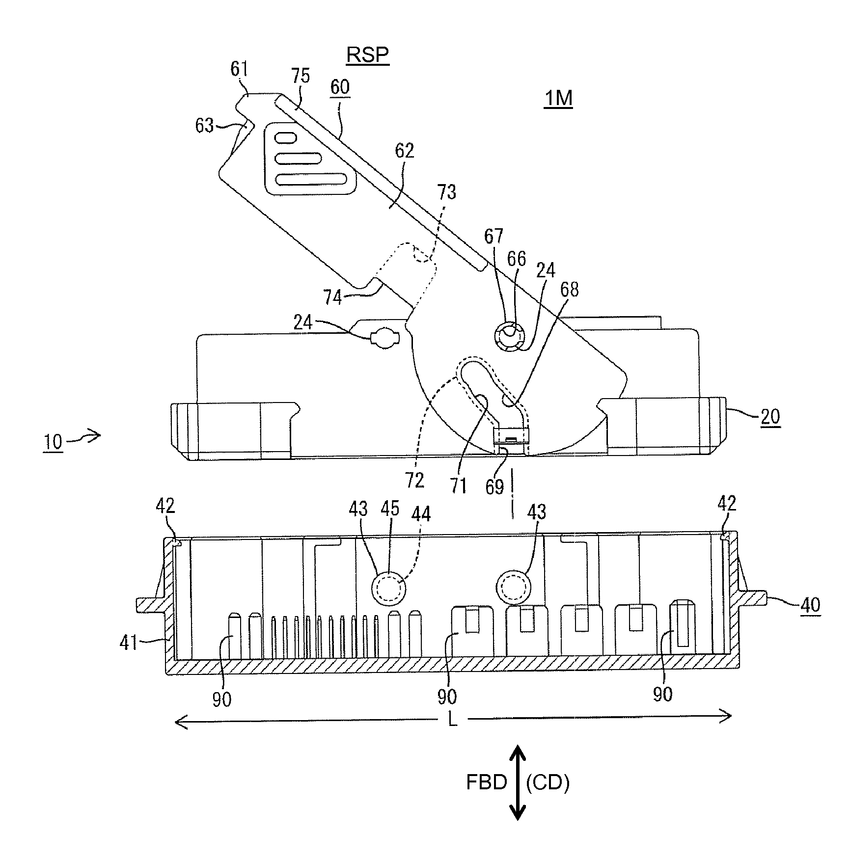
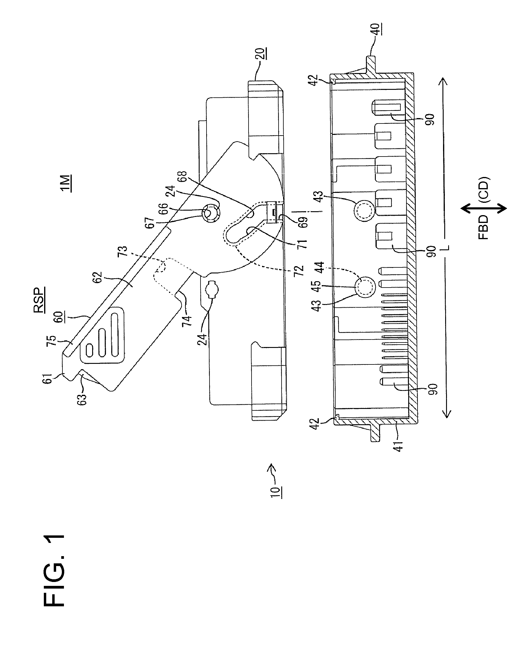
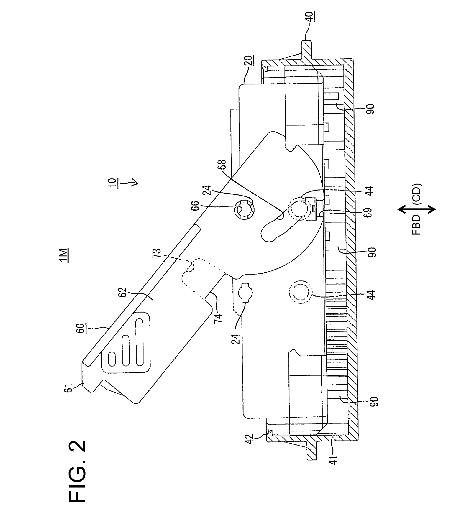
[0025]A connector assembly in accordance with the invention is illustrated in FIGS. 1 to 8 and is identified generally by the numeral 10. The connector assembly 10 has a first housing 20 and a second housing 40 that are connectable with each other along a connecting direction CD. A lever 60 is mounted rotatably on the first housing 20. In the following description, ends of the two housings 20, 40 that are to be connected are referred to as front ends concerning forward and backward directions FBD, and the left side of FIG. 1 is referred to an upper side concerning a vertical direction.

[0026]The second housing 40 is made e.g. of synthetic resin and constructed as a male housing for receiving male terminal fittings. The second housing 40 includes a substantially rectangular tubular receptacle 41 that is long and narrow in a lengthwise direction L that is substantially orthogonal to a connecting direction CD. Large and small tabs 90 of male terminal fittings project into the receptacle...


PUM


Abstract

Two supports (24) are formed on one side surface of a first housing (20) at positions symmetrical to a center of a connection area with a second housing (40) in a lengthwise direction (L). The lever (60) is selectively mounted in a first mode on one of the two supports (24) and rotated toward one side or in a second mode on the other support (24) and rotated toward the other side. The lever (60) has a first and second parts for exerting pushing forces on the first housing (20) in a direction to proceed with a connecting operation of the housings (20, 40) as the lever (60) is rotated. The first part is a cam groove (68) engageable with a follower pin (43) of the second housing (40) and the second part is a recessed groove (73) engageable with the support (24) not supporting the lever (60).

Description

BACKGROUND OF THE INVENTION[0001]1. Field of the Invention[0002]The invention relates to a lever-type connector and to a connector assembly and to a connecting method therefor.[0003]2. Description of the Related Art[0004]Japanese Unexamined Patent Publication No. 2004-288442 discloses a connector with first and second housings that are connectable with one another. A lever is supported rotatably on a support on a side surface of the first housing and a cam groove is formed in the lever. The cam groove can engage a follower pin that projects from the second housing. The follower pin slides on a surface of the cam groove as the lever is rotated to create a pressing force in a direction to assist a connecting operation of the two housings. As a result, the two housings are connected with each other with a small connecting force.[0005]The support and the cam groove of the above-described connector are displaced toward one side from the longitudinal center of a connection area of the fir...

Claims


Application Information

Patent Timeline
Patent Type & Authority Applications(United States)
IPC IPC(8): H01R13/62H01R13/627
CPCH01R13/62955H01R13/62938H01R13/629
Inventor SHAMOTO, WATARUMAKINO, KENJI
Owner SUMITOMO WIRING SYST LTD
Why Eureka
Try Eureka