Method and Receiver for Identifying a Leading Edge Time Period in a Received Radio Signal

a technology of leading edge time and received radio signal, which is applied in the direction of transmission monitoring, instruments, measurement devices, etc., can solve the problem of not being able to accurately identify the time period having the maximum average received energy

Inactive Publication Date: 2009-07-02
MITSUBISHI ELECTRIC RES LAB INC
View PDF12 Cites 27 Cited by
  • Summary
  • Abstract
  • Description
  • Claims
  • Application Information

AI Technical Summary

Benefits of technology

[0018]According to another embodiment of the present invention there is provided a novel computer program product storing a program which when executed by a processor in a receiver configured to identify a leading edge time period of a received radio signal causes the processor to perform identifying a greatest energy time period in a sequence of time periods, the received radio signal having a greatest average energy in the greatest energy time period; and identifying as the leading edge time period a latest time period preceding the greatest energy time period immediately following a number of adjacent low energy time periods, the received radio signal having an average energy greater than or equal to a threshold energy in the leading edge time period, and the received radio signal having an average energy less than the threshold energy in each of the adjacent low energy time periods.

Problems solved by technology

Thus, it may not be accurate to identify the time period having the maximum average received energy as the leading edge of the received signal.

Method used


Image

  • Method and Receiver for Identifying a Leading Edge Time Period in a Received Radio Signal
  • Method and Receiver for Identifying a Leading Edge Time Period in a Received Radio Signal
  • Method and Receiver for Identifying a Leading Edge Time Period in a Received Radio Signal

Examples


Embodiment Construction

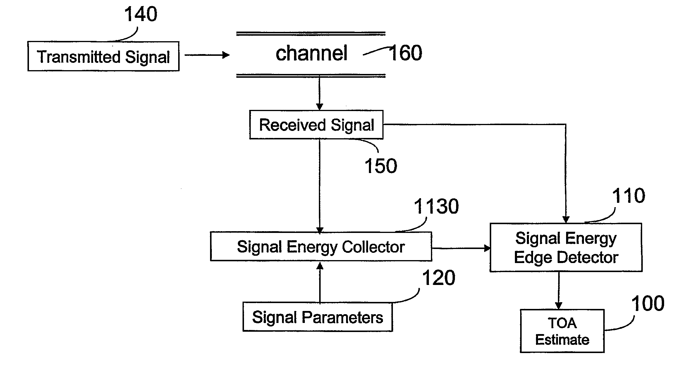
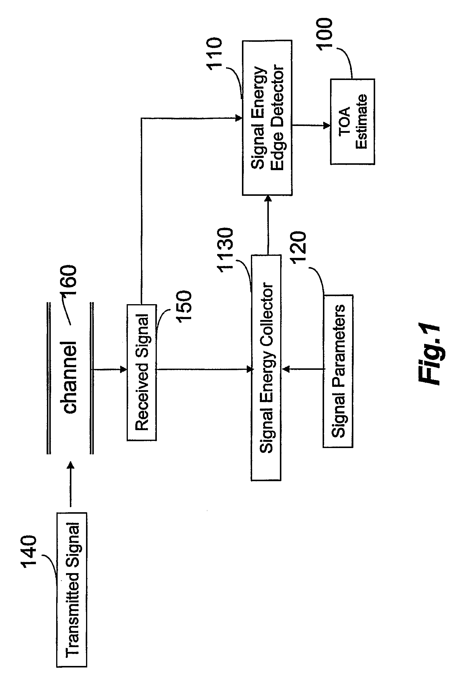
[0036]Referring to further of the drawings, wherein like reference numerals designate identical or corresponding parts throughout the several views, and more particularly to FIG. 1 thereof, FIG. 1 shows a block diagram of a receiver according to an embodiment of the present invention. The receiver includes a signal energy edge detector 110 that receives the received signal 150 and the average energy of the received signal in each time period as determined by the signal energy collector 1130. The signal energy collector 1130 and the signal energy edge detector 110 receive the received signal 150, which results from transmission of the transmitted signal 140 over the radio channel 160. The signal energy edge detector produces a TOA estimate 100.

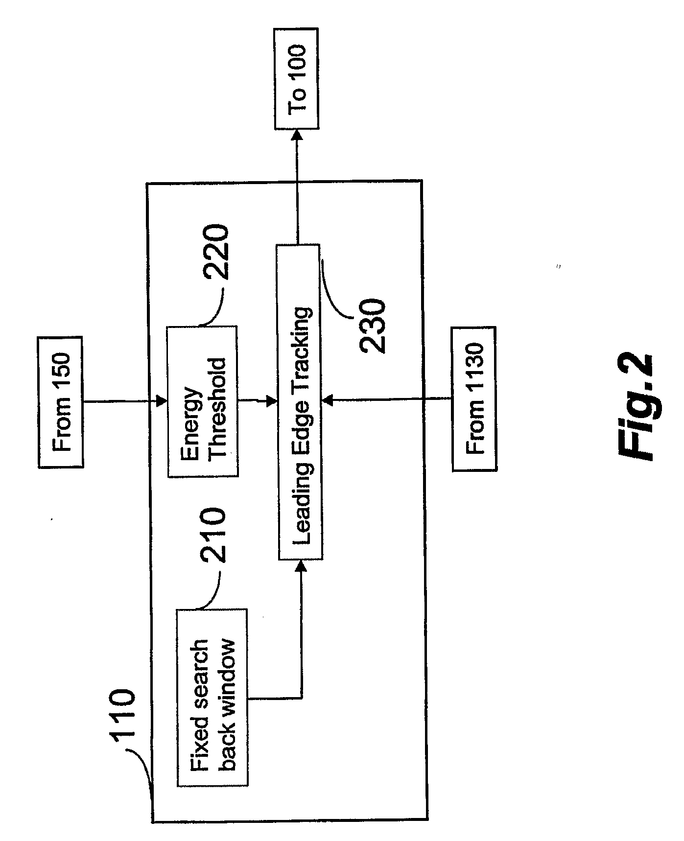
[0037]FIG. 2 is a detailed block diagram of the signal energy edge detector 110 that includes a fixed search back window section 210, energy threshold section 220 and leading edge tracking section 230. The energy threshold section 220 sets an e...


PUM


Abstract

A method for identifying a leading edge time period of a received radio signal includes identifying a greatest energy time period in a sequence of time periods. The received radio signal has a greatest average energy in the greatest energy time period. The method also includes identifying a least energy time period in the sequence of time periods. The received radio signal has a least average energy in the least energy time period. Further, the method includes setting a threshold energy based on the greatest average energy and the least average energy, determining a number of window time periods based on a characteristic of a radio channel used by the received radio signal, and identifying as a leading edge time period an earliest time period that precedes the greatest energy time period within the number of window time periods. The received radio signal in the leading edge time period has an average energy greater than or equal to the threshold energy.

Description

CROSS REFERENCE TO RELATED APPLICATIONS[0001]The present invention is related to PCT / US2005 / 013035, entitled METHOD AND SYSTEM FOR ESTIMATING TIME OF ARRIVAL OF SIGNALS USING MULTIPLE DIFFERENT TIME SCALES, filed Apr. 15, 2005 and PCT / US2005 / 013590, entitled TRANSMITTING SIGNALS FOR TIME OF ARRIVAL ESTIMATION, filed Apr. 22, 2005, each of which are incorporated by reference herein in their entirety.BACKGROUND OF THE INVENTION[0002]1. Field of the Invention[0003]The present invention relates generally to methods and apparatuses for determining a distance between a radio transmitter and receiver by accurately identifying a time-of-arrival (TOA) of a leading edge of a received radio signal, and more particularly to identifying a leading edge time period in a wireless personal area network (WPAN) according to the IEEE 802.15 standard.[0004]2. Background of the Invention[0005]There is a growing demand for location awareness and ranging in short-range communication networks, and applicati...

Claims


Application Information

Patent Timeline
Patent Type & Authority Applications(United States)
IPC IPC(8): H04B17/00G01S19/03G01S19/22
CPCH04B1/7183H04B1/71637
Inventor MOLISCH, ANDREAS F.GUVENC, ISMAILSAHINOGLU, ZAFER
Owner MITSUBISHI ELECTRIC RES LAB INC
Why Eureka
Try Eureka