
Deflectable catheter constructed to inhibit component migration

a technology of component migration and deflectable catheters, which is applied in the field of deflectable ep catheters, can solve the problems of affecting the configuration of the lumen relative to the components, and the inability to control the functionality of the electrode that connects to the broken wire. , to achieve the effect of cross-sectional

Inactive Publication Date: 2009-07-02
ST JUDE MEDICAL ATRIAL FIBRILLATION DIV
View PDF8 Cites 3 Cited by
  • Summary
  • Abstract
  • Description
  • Claims
  • Application Information

AI Technical Summary

Benefits of technology

[0010]A further embodiment of the method according to the present teachings includes constructing a shaft having a proximal end, a distal end, and at least one lumen disposed within the shaft. In this embodiment, the constructing step includes constructing the distal end to have a first portion and a second portion. The first portion has a first outer diameter, and at least one region of the second portion has a second outer diameter that is greater than the first outer diameter. As with the embodiment described above, this embodiment of the method further includes inserting a component in the lumen. The method still further includes processing at least the regions of the second portion of the distal end that have the enlarged second diameter such that the cross-sectional profile of the lumen is reduced to capture / confine the component disposed therein. This process causes the second outer diameter to become substantially equal to the first outer diameter.

Problems solved by technology

These conventional arrangements, however, are not without their drawbacks.
One particular drawback lies in the configuration of the lumen relative to the components disposed therein.
Consequently, the wire may break, thereby disabling the functionality of the electrode that connects to the broken wire.

Method used


Image

  • Deflectable catheter constructed to inhibit component migration
  • Deflectable catheter constructed to inhibit component migration
  • Deflectable catheter constructed to inhibit component migration

Examples


Embodiment Construction

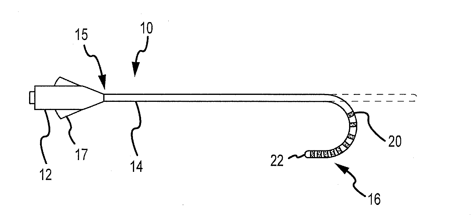
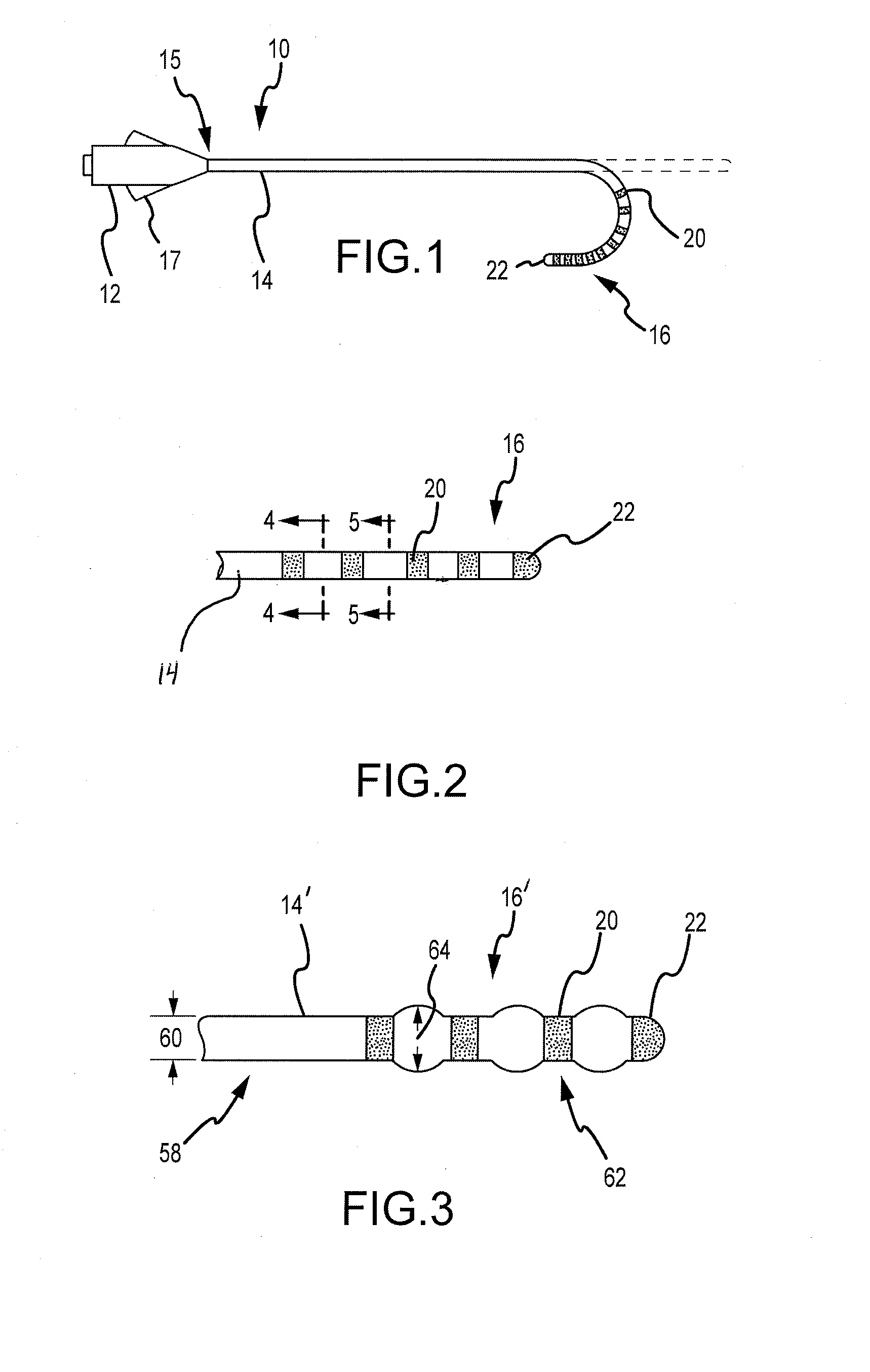
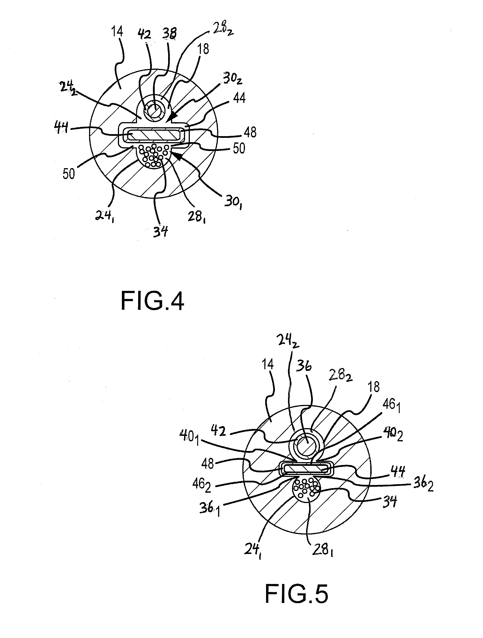
[0021]Referring now to the drawings wherein like reference numerals are used to identify identical components in the various views, FIG. 1 illustrates one exemplary embodiment of a deflectable electrophysiological catheter 10. In its most general form, the catheter 10 includes a handle portion 12 and an elongated shaft portion 14, wherein shaft 14 extends along an axis and includes a proximal end 15 and a distal end 16. The catheter 10 may be used in a number of diagnostic and therapeutic applications, such as the recording of electrograms in the heart, the performance of a cardiac ablation procedure, and other similar applications / procedures. Accordingly, one of ordinary skill in the art will recognize and appreciate that the inventive catheter and method of manufacturing the same can be used in any number of diagnostic and therapeutic applications.

[0022]With continued reference to FIG. 1, the handle 12 is coupled to the shaft 14 at the proximal end 15. The handle 12 is operative t...


PUM

PropertyMeasurementUnit
sizeaaaaaaaaaa
outer diameteraaaaaaaaaa
diameteraaaaaaaaaa

Abstract

A method of manufacturing a deflectable electrophysiological catheter includes constructing a shaft having a distal end and at least one lumen. The method further includes inserting a component into the lumen, and processing at least a portion of the distal end to reduce the cross-sectional profile of the lumen to capture / confine the component. A catheter manufactured using this method includes a shaft having at least one lumen. The lumen comprises a longitudinally-extending trough defined by a longitudinally-extending recess, within which a component is disposed, and a longitudinally extending open edge. The lumen further comprises a longitudinally-extending channel defined by a longitudinally-extending cavity and by the open edge of the trough. A planarity wire is disposed within the cavity and is configured to close the open edge of the trough to within a pre-defined tolerance that is less than the size of the component to retain the component in the recess.

Description

BACKGROUND OF THE INVENTION[0001]a. Field of the Invention[0002]The present invention relates to electrophysiological (EP) catheters. More particularly, the present invention relates to a deflectable EP catheter constructed to inhibit component migration.[0003]b. Background Art[0004]It is known to use catheters to perform a variety of functions relating to diagnostic and therapeutic medical procedures. EP catheters find particular application in cardiac electrophysiology studies and procedures, such as various cardiac diagnostic and / or ablation procedures. In such studies / procedures, electrical signals from the heart may be conducted through electrodes disposed at the distal end of the catheter to monitoring and recording devices associated with the catheter. The electrodes may also be used for other purposes such as delivering energy to the heart as stimulus to monitor the heart's response thereto or to ablate a site of cardiac tissue that causes, for example, an arrhythmia or abno...

Claims


Application Information

Patent Timeline
Patent Type & Authority Applications(United States)
IPC IPC(8): A61M25/092
CPCA61B18/1492A61B2017/00526A61B2018/00839A61M25/0009A61M25/0069A61M25/0082Y10T29/4913A61M25/0147Y10T29/49169Y10T29/49194Y10T29/49174Y10T29/49185A61M25/0144
Inventor HASTINGS, JOHN M.LATRAILLE, GARY B.YOUNGER, ELIZABETH
Owner ST JUDE MEDICAL ATRIAL FIBRILLATION DIV
Features
  • Generate Ideas
  • Intellectual Property
  • Life Sciences
  • Materials
  • Tech Scout
  • Unparalleled Data Quality
  • Higher Quality Content
  • 60% Fewer Hallucinations
Learn More