Computer-aided method for predicting particle uptake by a surface of a moving object

a technology of moving objects and computer-aided methods, applied in cad techniques, instruments, analogue processes for specific applications, etc., can solve problems such as weight increase, aerodynamic behavior change, and aerodynamic shape change, and achieve the effect of minimizing the necessary computation resources

Inactive Publication Date: 2009-07-02
AIRBUS OPERATIONS SL
View PDF19 Cites 14 Cited by
  • Summary
  • Abstract
  • Description
  • Claims
  • Application Information

AI Technical Summary

Benefits of technology

[0017]An object of the present invention is to provide a computer-aided method for predicting water particle uptake, or the uptake of other particles, by the surface of an object moving in a flow current, such as an aircraft, subjected to a shower of said particles, minimizing the necessary computation resources for that purpose.

Problems solved by technology

There are many types of problems caused by ice in airplanes.
This can cause a weight increase and a change in the aerodynamic shape especially in the leading edges of wings, tail stabilizers and engine air intake ducts.
In airfoils with ice, the aerodynamic behavior changes dramatically in a low-speed landing configuration: the lift is reduced, the drag increases and they can unexpectedly stall.
Due to the ice in the horizontal and vertical stabilizers, the airplane can lose side or longitudinal control.
The largest ice particles, which break upon coming into contact with the engine air intake ducts, can damage the blades or sensors of the turbofans.
This process requires carrying out as many uptake calculations as different particle sizes considered in the distribution, as it is not possible to use different particle sizes in the same calculation because the local uptake parameter calculation is based on the hypothesis that all the particles that come out within triangle A1 impact on the triangle defined by A2 (mass continuity condition), which hypothesis is only valid if it is considered that all the particles have the same size.
The method known in the art therefore has a high computation cost, especially when working with very complex geometries.

Method used


Image

  • Computer-aided method for predicting particle uptake by a surface of a moving object
  • Computer-aided method for predicting particle uptake by a surface of a moving object
  • Computer-aided method for predicting particle uptake by a surface of a moving object

Examples


Embodiment Construction

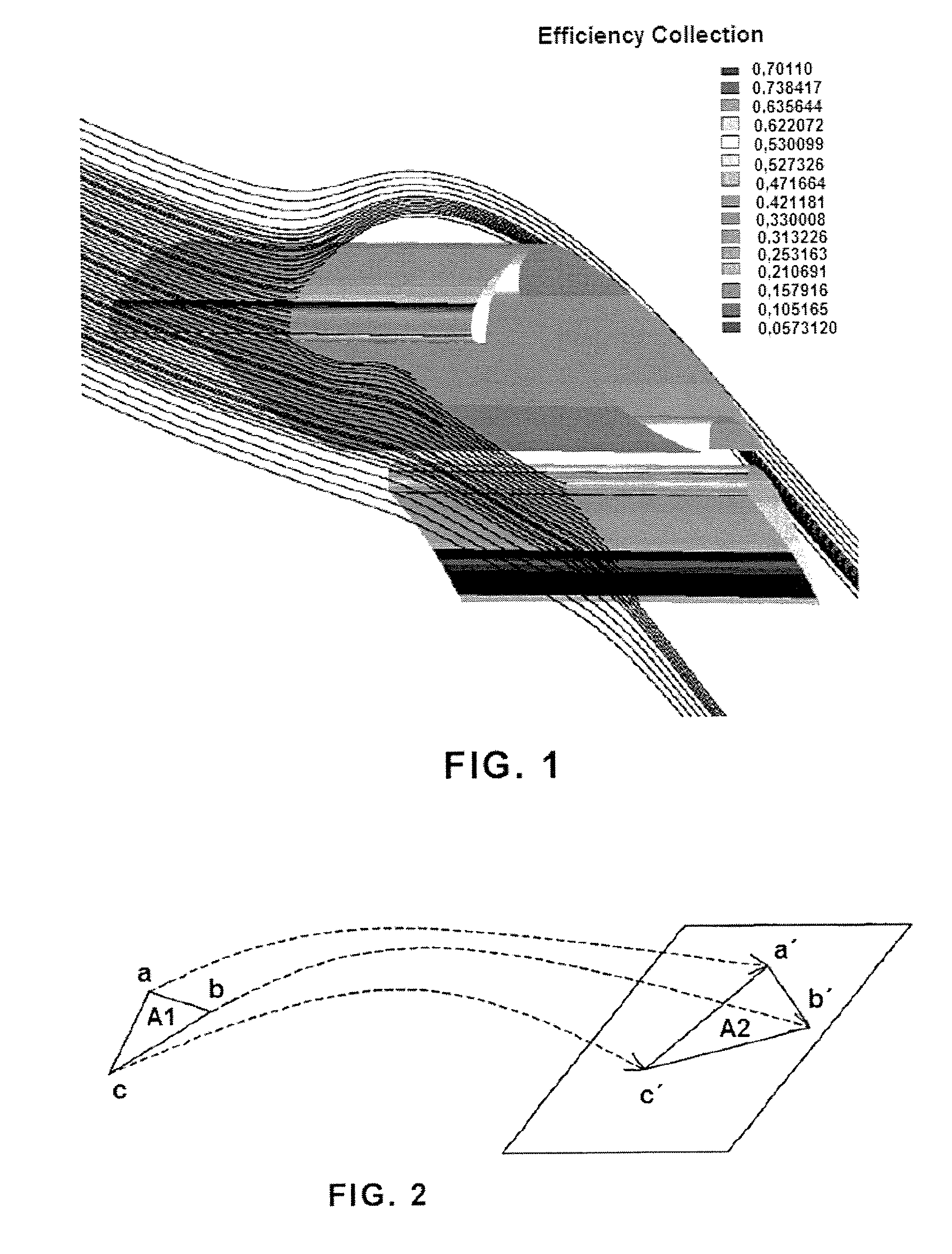
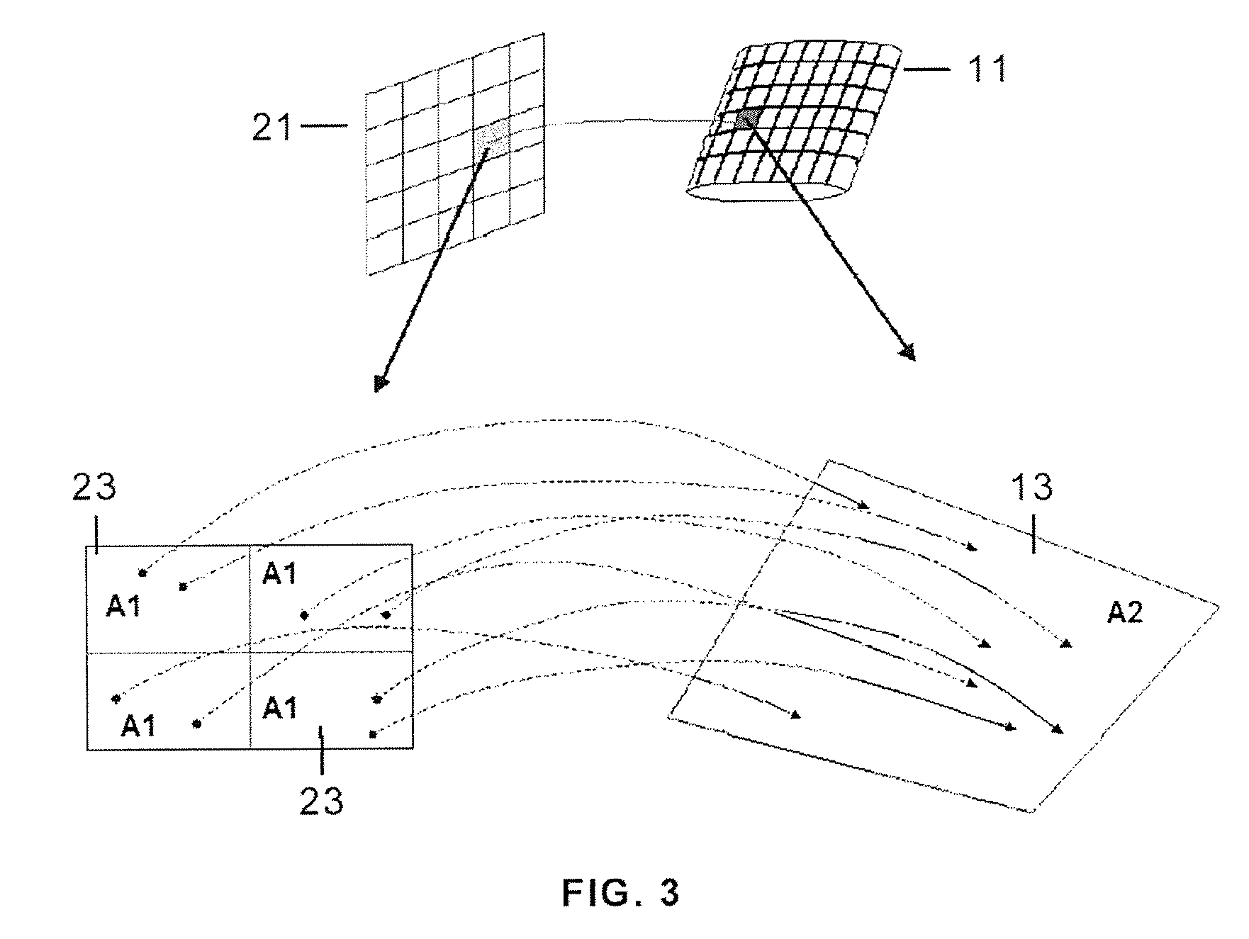
[0027]An embodiment of the computer-aided method for predicting water droplet uptake by an aerodynamic aircraft surface comprising the following stages: Model Preparation, Calculation and Simulation and Analysis, will be described below, essentially with reference to FIG. 3.

I. Model Preparation

[0028]A finite element model is prepared like in the method known in the art, importing the structural geometry of the aerodynamic surface 11.

[0029]For the specific purposes of the method object of the present invention, the model includes on one hand a water droplet projection area 21 formed by a mesh of cells 23 with an identical size, and on the other hand, the aerodynamic surface 11 formed by a mesh of cells 13 to enable the simulation of the paths of the droplets projected from area 21 and the determination of which of them impact the aerodynamic surface 11.

[0030]One and the same water droplet distribution is assigned to each cell 23, which distribution can be that characterized by Langmu...


PUM


Abstract

The invention relates to a computer-aided method for predicting particle uptake by a surface of an object moving in a flow current, comprising the following steps: preparing a discrete model of said object and the surrounding flow, including a projection area (21) for projecting said particles formed by a mesh of cells (23) with an identical size, and a mesh of cells (13) of said surface (11); simulating the projection of particles with a different size from said projection area (21) on the surface (11), both the density Di of projected particles and their size distribution being identical for the cell (23); obtaining for each cell (13) of said surface (11) the local uptake efficiency parameter β by dividing the density Df of particles impacting against said cell (13) by the density Di of particles projected from the projection area (21).

Description

FIELD OF THE INVENTION[0001]The present invention relates to a computer-aided method for predicting particle uptake by a surface of an object moving in a flow current and more particularly, for predicting water droplet uptake by an aircraft surface.BACKGROUND OF THE INVENTION[0002]The authorities require the certification that aircraft meet certain requirements so that they can fly, which requirements ensure their operability in meteorological conditions favoring continuous or intermittent ice formation.[0003]There are many types of problems caused by ice in airplanes. During the landing, the airplane can descend with an intermediate speed from a cold and dry flight altitude to a normal situation on the ground passing through cloudy areas in which moisture or water particles can freeze on the airplane surfaces that are still cold. This can cause a weight increase and a change in the aerodynamic shape especially in the leading edges of wings, tail stabilizers and engine air intake du...

Claims


Application Information

Patent Timeline
Patent Type & Authority Applications(United States)
IPC IPC(8): G06G7/57G06F17/10G06G7/72
CPCG06F2217/16G06F17/5018G06F30/23G06F2111/10
Inventor APARICIO DURAN, JOSE ANTONIOALONSO RODRIGUEZ, JOSE MANUEL
Owner AIRBUS OPERATIONS SL
Why Eureka
Try Eureka