Fluid separator for a compressor

Active Publication Date: 2009-07-09
HANON SYST
View PDF17 Cites 33 Cited by
  • Summary
  • Abstract
  • Description
  • Claims
  • Application Information

AI Technical Summary

Benefits of technology

[0017]Advantages of the above invention include a greater amount of oil returned to the compressor to ensure adequate sealing, less oil in t

Problems solved by technology

Although the technologies improve fuel economy, there are drawbacks.
One such drawback is that accessories powered by a fuel-powered engine no longer operate when the fuel-powered engine is not in operation.
A significant disadvantage of the full electric compressor is the inefficiency that occurs from converting engine shaft power to electricity, then el

Method used


Image

  • Fluid separator for a compressor
  • Fluid separator for a compressor
  • Fluid separator for a compressor

Examples


Embodiment Construction

[0022]The following detailed description and appended drawings describe and illustrate an exemplary embodiment of the present invention. The description and drawings serve to enable one skilled in the art to make and use the invention, and are not intended to limit the scope of the invention in any manner. It is understood that materials other than those described can be used without departing from the scope and spirit of the invention.

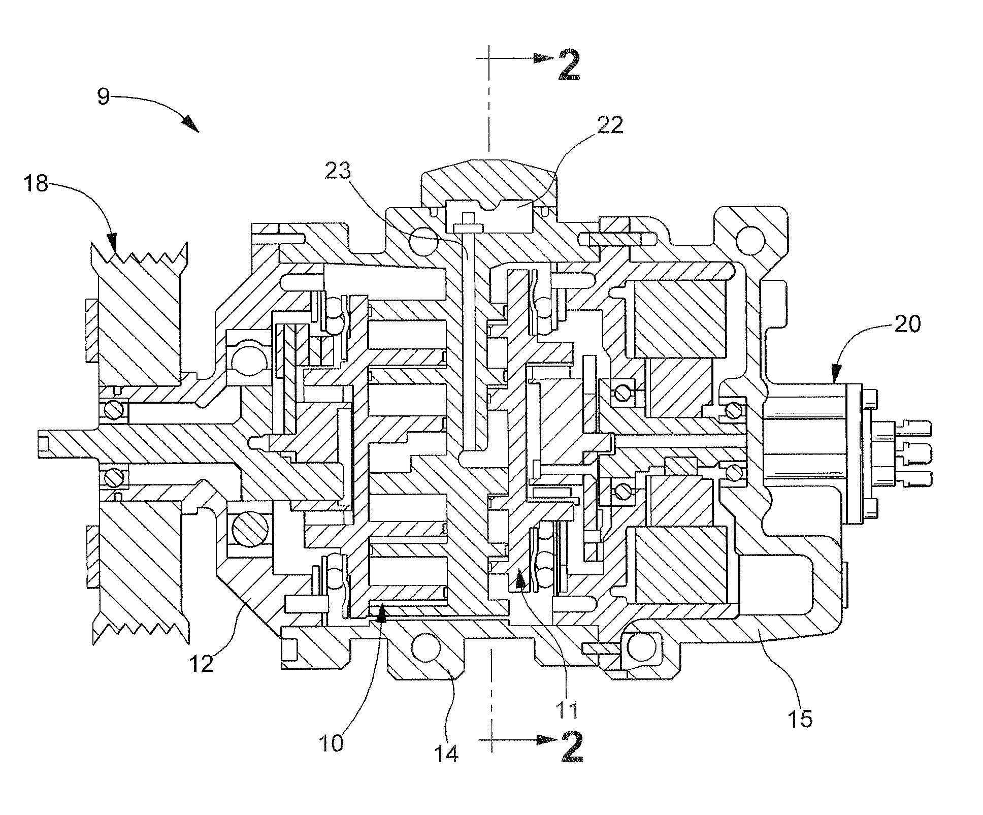
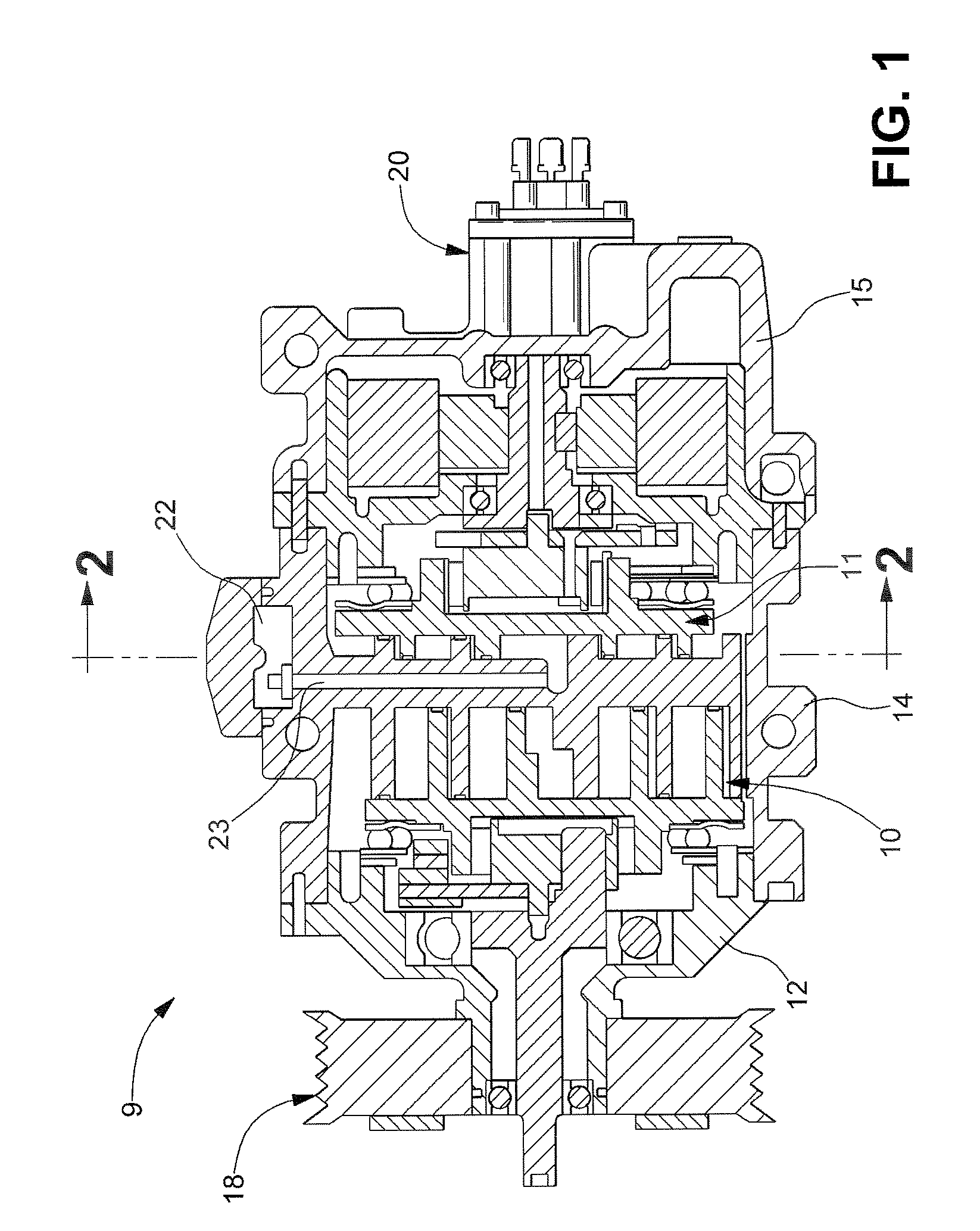
[0023]FIG. 1 shows a compressor 9 according to an embodiment of the invention. Although the compressor 9 in the embodiment shown is a hybrid scroll compressor, it is understood that the compressor 9 can be other compressor types if desired. In the embodiment shown, the compressor 9 includes a housing assembly having a first compression assembly 10 and a second compression assembly 11 disposed therein. The housing assembly includes a first housing shell 12, a second housing shell 14, and a third housing shell 15. The first housing shell 12, the second ...


PUM

PropertyMeasurementUnit
Flow rateaaaaaaaaaa

Abstract

A fluid separator for a compressor is disclosed including a hollow main body having an annular flange and an annular collar formed thereon, wherein the annular collar includes an annular array of apertures formed therein for separating a liquid from a fluid and attenuating pressure pulsations of the fluid.

Description

FIELD OF THE INVENTION[0001]The invention relates to a compressor and more particularly to a fluid separator having an annular array of apertures formed therein adapted to separate a liquid from a fluid and attenuate pressure pulsations of the fluid.BACKGROUND OF THE INVENTION[0002]Hybrid electric vehicles having improved fuel economy over internal combustion engine and other vehicles are quickly becoming more popular as a cost of traditional fuel increases. Typically, the improved fuel economy is due to known technologies such as regenerative braking, electric motor assist, and engine-off operation.[0003]Although the technologies improve fuel economy, there are drawbacks. One such drawback is that accessories powered by a fuel-powered engine no longer operate when the fuel-powered engine is not in operation. One major accessory that does not operate is an air-conditioning compressor, which cools air in a passenger compartment of the vehicle. Ultimately, without the use of the compr...

Claims


Application Information

Patent Timeline
IPC IPC(8): F04B53/18B60H1/32F04B17/03F04C29/02F04B35/04F04B17/00
CPCF04C18/0215F04C23/001F25B2400/02F04C2240/45F04C29/026Y10S418/01
Inventor BHATIA, KANWALTHEODORE, JR., MICHAEL GREGORY
Owner HANON SYST
Why Eureka
Try Eureka