Levitation type support unit

a support unit and floor technology, applied in the direction of machine supports, other domestic objects, measuring instruments, etc., can solve the problems of noise generation between floors, noise generation between floors can be serious, support structures of supported objects can be worn away or damaged, etc., to achieve easy replacement of parts, vibration and noise generation between floors

Inactive Publication Date: 2009-07-09
YEIL M&C
View PDF3 Cites 2 Cited by
  • Summary
  • Abstract
  • Description
  • Claims
  • Application Information

AI Technical Summary

Benefits of technology

[0027]According to the present invention, various kinds of objects can be supported by a levitation type supporting unit, and the objects can endure fatigue load, etc. even through the period of the supporting unit being used increases.
[0028]Particularly, the supporting unit supports an object according to levitation method so that vibration and noises generated

Problems solved by technology

Such frequency of vibration approaches an audio frequency band, thereby generating noises.
Particularly, a type of dwelling in a house such as an apartment has been recently generalized so that a problem of noises generated between floors becomes serious.
However, the conventional supporting structure of a supported object can be worn away or be damaged, and particularly, vibrations of the supported object are transferred while making direct contact with the supporting structure of the supported object so that the vibration cannot be effectively absorbed.
Therefore, vibration an

Method used


Image

  • Levitation type support unit
  • Levitation type support unit
  • Levitation type support unit

Examples


Embodiment Construction

[0044]Hereinafter, exemplary embodiments of the present invention will be described with reference to the accompanying drawings.

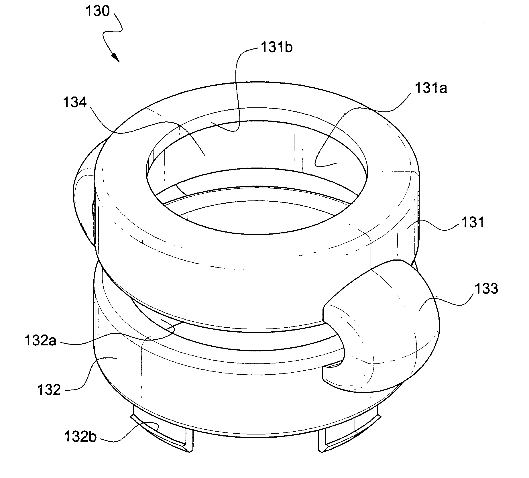
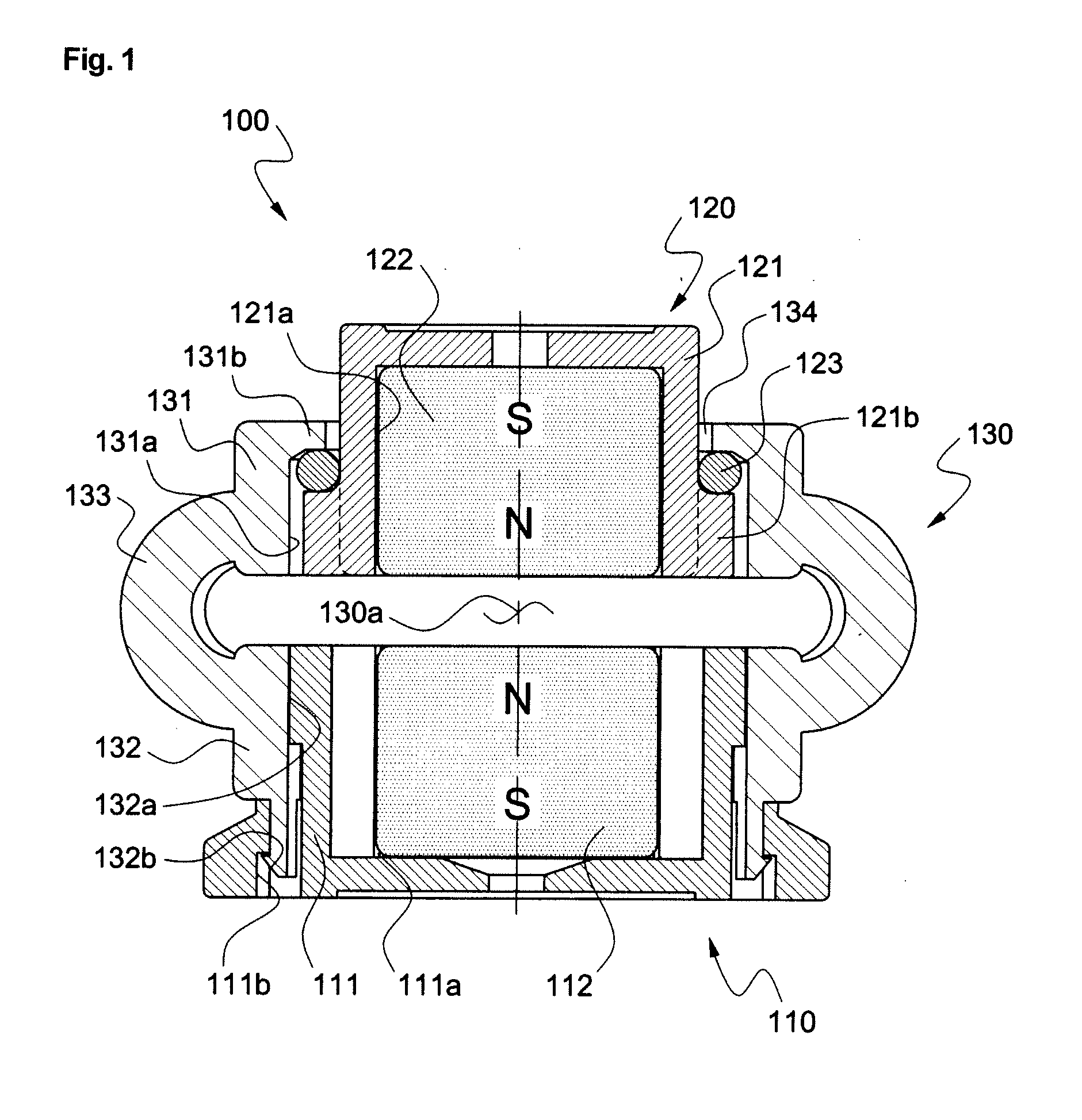
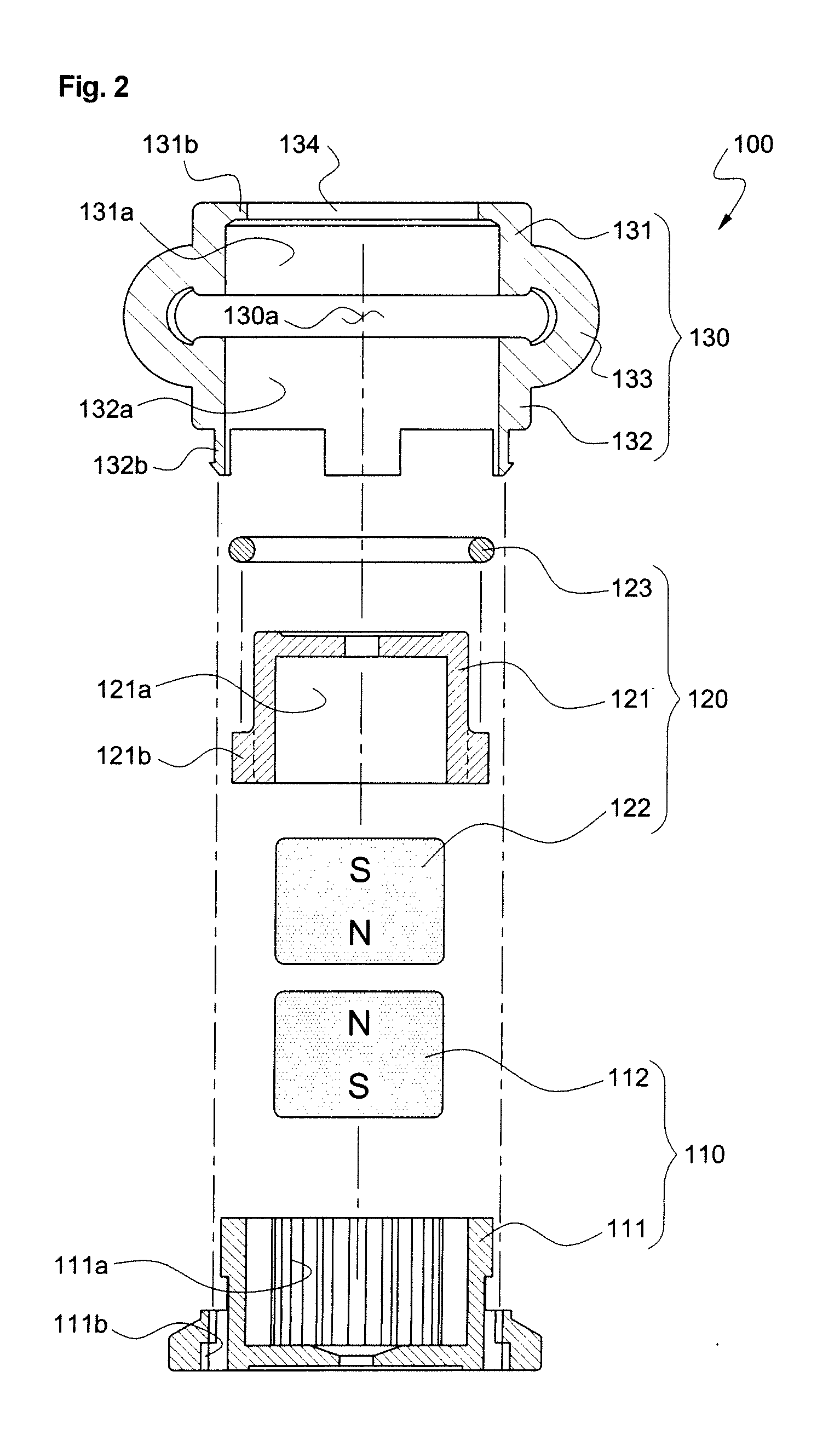
[0045]As shown in FIGS. 1 and 2, a supporting unit 100 using a levitation method according to an embodiment of the present invention includes a lower magnet part 110, an upper magnet part 120, and a fixing part 130.

[0046]As shown in FIG. 2, the lower magnet part 110 includes a lower casing 111 and a lower magnet 112. As shown in FIGS. 6 and 7, which illustrate another embodiment of the present invention, the lower magnet part 110 can further include a lower packing 113 assembled with a lower part of the lower casing 111. Accordingly, a contacting force between a lower surface of the supporting unit 100 and an installing surface thereof can increase due to the lower packing 113.

[0047]As shown in FIG. 2, the lower casing 111 includes a lower magnet receiving space 111a for receiving the lower magnet 112 and an engaging part 111b with which a locking part 132b...


PUM


Abstract

Disclosed is a levitation type supporting unit interposed between an object to be supported and an installing surface so as to support the object respective to the installing surface. The supporting unit includes a lower magnet part having a lower magnet; an upper magnet part arranged at an upper part of the lower magnet part while having an interval in such a manner as to be spaced from the lower magnet part, the upper magnet part having a surface facing the lower magnet, a polarity of the surface being equal to a polarity of a corresponding surface of the lower magnet; an upper fixing cap being assembled with the upper magnet part so as to allow the upper magnet part to be elevated; a lower fixing cap which is connected with the upper fixing cap and is assembled with the lower magnet part; and a fixing part including a connecting part formed at one side between the upper fixing cap and the lower fixing cap, the connecting part connecting the upper fixing cap and the lower fixing cap while having an interval in such a manner that space formed between the upper fixing cap and the lower fixing cap is exposed, the fixing part preventing the upper magnet part from escaping from an upper position of the lower magnet part. The supporting unit supports the object respective to the installing surface in a levitation manner so that vibration of the object to be supported and noises caused by the vibration can be reduced, and vibrations and noises, which are generated between floors in residential space such as an apartment, can be minimized. Also, the supporting unit allows an observer to directly identify a state of the object being supported in the levitation manner by the naked eyes.

Description

BACKGROUND OF THE INVENTION[0001]1. Field of the invention[0002]The present invention relates to a levitation type support unit, and more particularly to a levitation type support unit interposed with an object to be supported and an installing surface by using a repulsive force between magnets so as to support the object with respect to the installing surface.[0003]2. Description of the Prior Art[0004]When articles (hereinafter, collectively referred to as “objects to be supported”), such as speakers, automatic washers, or sporting equipment, are used, vibrations are generated within the objects to be supported, themselves. Such frequency of vibration approaches an audio frequency band, thereby generating noises.[0005]Particularly, a type of dwelling in a house such as an apartment has been recently generalized so that a problem of noises generated between floors becomes serious.[0006]In order to decrease such vibrations of the object to be supported and noises caused by the vibrat...

Claims


Application Information

Patent Timeline
IPC IPC(8): G01R1/16
CPCF16F6/005F16F15/02F16F15/03
Inventor HAM, DUCKCHUN
Owner YEIL M&C
Why Eureka
Try Eureka