Liquid crystal display device and viewing angle control module

Active Publication Date: 2009-07-09
SHARP KK
View PDF13 Cites 67 Cited by
  • Summary
  • Abstract
  • Description
  • Claims
  • Application Information

AI Technical Summary

Benefits of technology

[0021]As described above, according to the liquid crystal display device of the present invention, an appropriate retardation member (for example, a ½ wavelength plate) is provided between the display liquid crystal panel and the viewing-angle-control liquid crystal panel. This make

Problems solved by technology

Therefore, the viewing restricted di

Method used


Image

  • Liquid crystal display device and viewing angle control module
  • Liquid crystal display device and viewing angle control module
  • Liquid crystal display device and viewing angle control module

Examples


Example

REFERENCE NUMERALS

[0042]1 Display Liquid Crystal Panel[0043]2 Viewing-Angle-Control Liquid Crystal Panel[0044]3 Backlight[0045]7 Setting Retardation Plate (λ / 2 Plate, Retardation Member)[0046]10 Liquid Crystal Display Device[0047]11 Liquid Crystal Cell[0048]12 Second Polarizing Plate[0049]13 First Polarizing Plate[0050]21 Liquid Crystal Cell[0051]22 Fourth Polarizing Plate[0052]23 Third Polarizing Plate[0053]24 Retardation Plate[0054]25 Retardation Plate[0055]49 Viewing Angle Control Module[0056]77a λ / 4 Plate (Retardation Member)[0057]77b λ / 4 Plate (Retardation Member)[0058]X12 Transmission Axis[0059]X22 Transmission Axis[0060]X23 Transmission Axis[0061]A Axis of Setting Retardation Plate (λ / 2 Plate)

BEST MODE FOR CARRYING OUT THE INVENTION

[0062]The following explains one embodiment of the present invention, with reference to FIGS. 1 through 17.

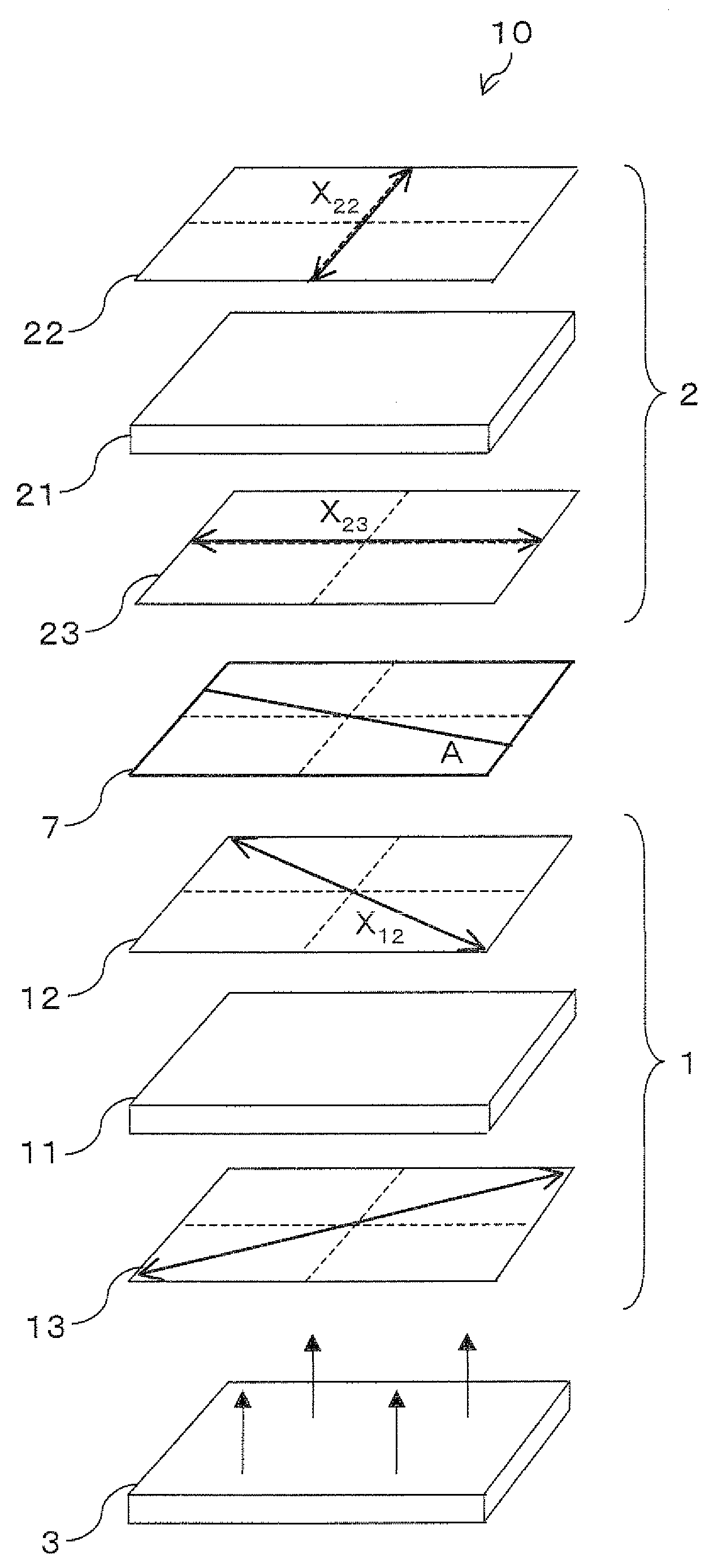
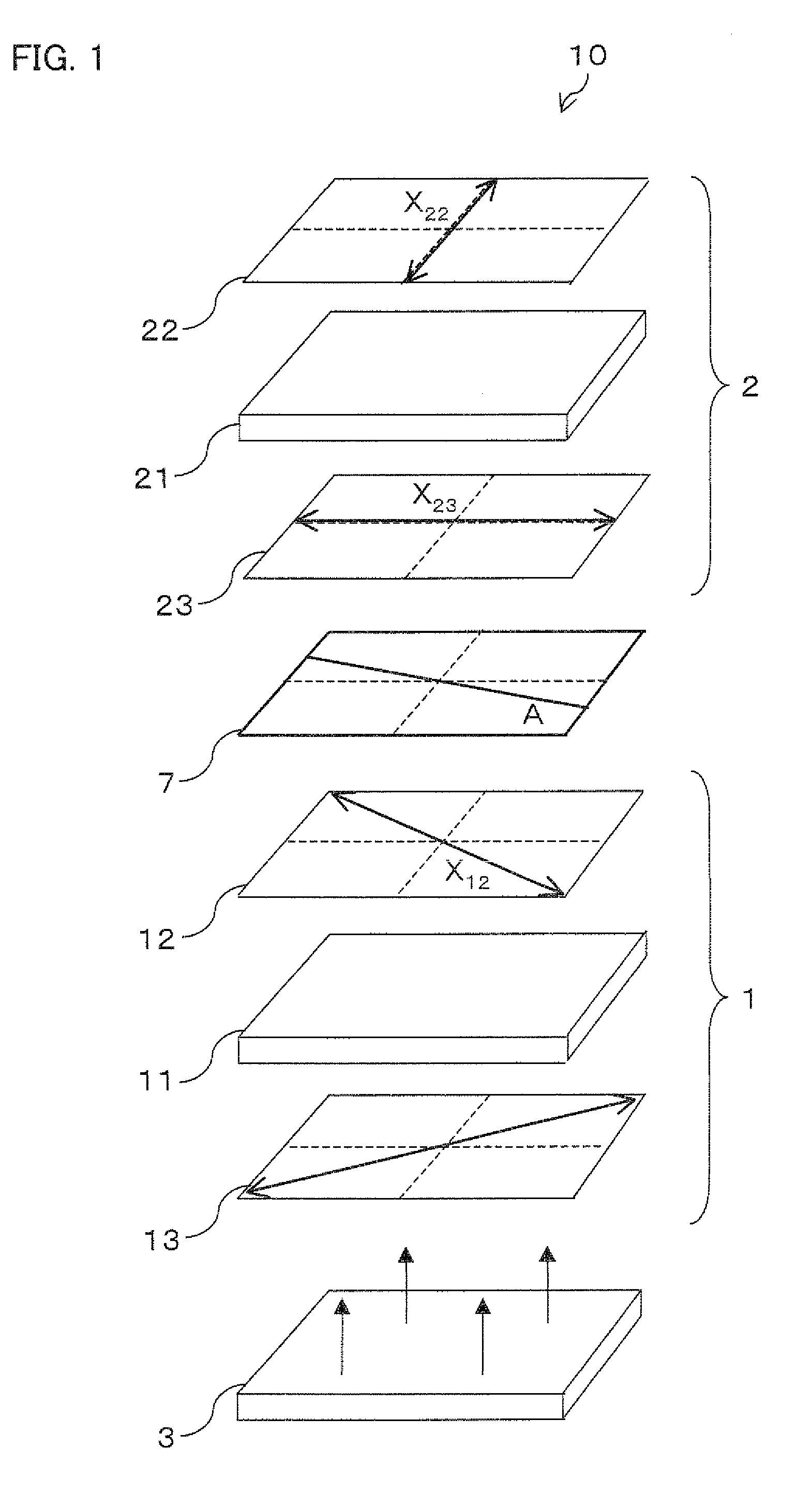
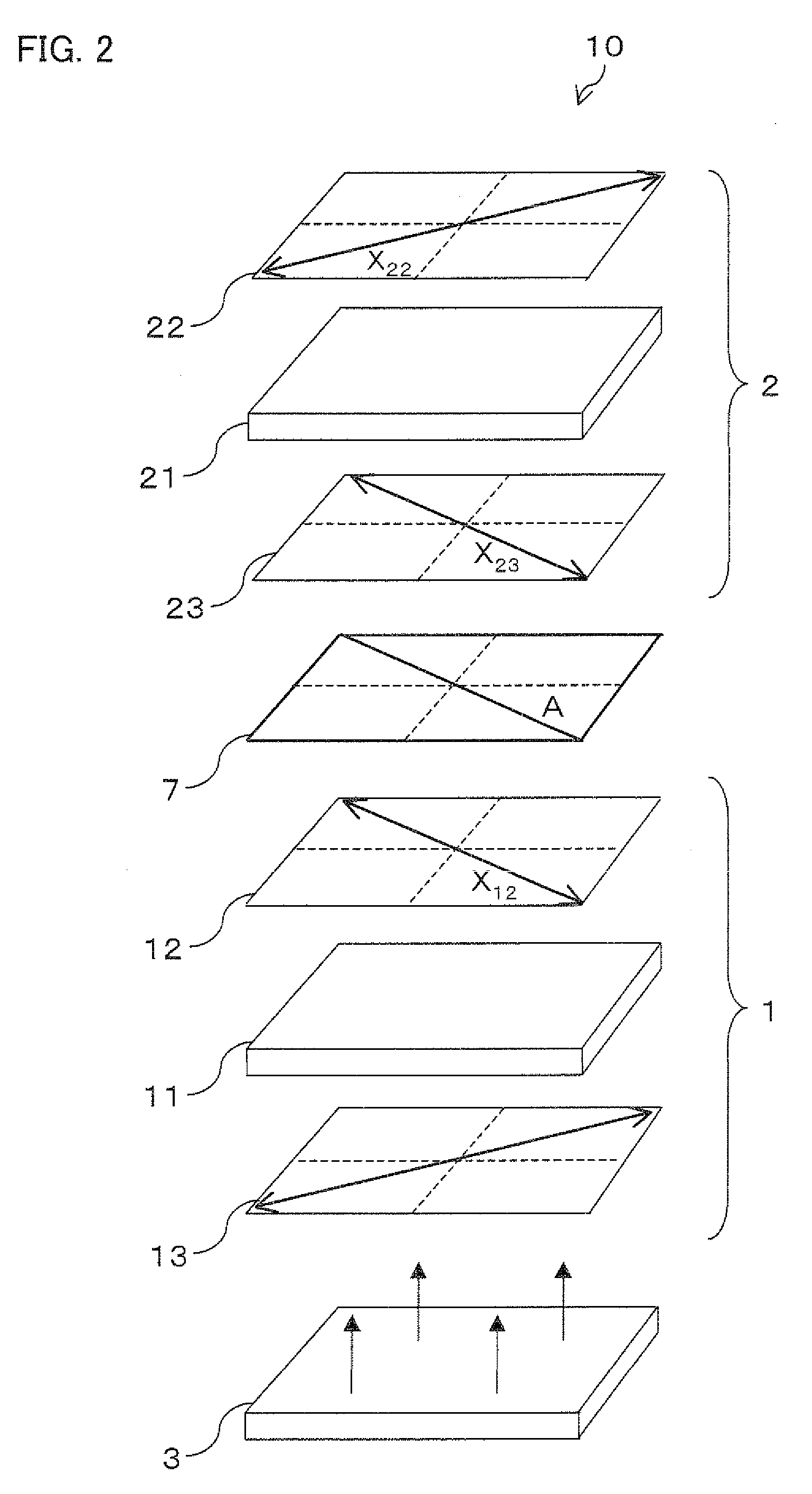
[0063]FIG. 3 is a cross sectional view schematically illustrating a liquid crystal display device 10 of the present invention. As illustrated...


PUM


Abstract

In a liquid crystal display device including a display liquid crystal panel and a viewing-angle-control liquid crystal panel and capable of switching viewing angle characteristics, a half wavelength plate for setting a viewing restricted direction is provided between the display liquid crystal panel and the viewing-angle-control liquid crystal panel. This makes it possible to realize a liquid crystal display device that allows a viewing restricted direction to be set as appropriate.

Description

TECHNICAL FIELD[0001]The present invention relates to a display device (e.g., a liquid crystal display device) capable of switching viewing angle characteristics.BACKGROUND ART[0002]In general, a display device is required to have a viewing angle characteristic (wide viewing angle characteristic) that allows a sharp image to be viewed from a larger number of viewing points. However, depending on an operation environment, it may be preferable that only a user can view displayed contents. It is highly likely that, for example, a laptop computer, a mobile information terminal (PDA: Personal Data Assistant), or a mobile phone is used in a place, such as a train or an airplane, where the general public is present. In such an operation environment, in view of security protection or privacy protection, it is desirable that the display device takes a viewing angle characteristic (a narrow viewing angle characteristic) with which only a user can view a displayed image (from a limited viewing...

Claims


Application Information

Patent Timeline
IPC IPC(8): G02F1/1347
CPCG02F1/13471G02F2413/08G02F2001/133638G02F1/1323G02F1/133638G02F1/1347G02F1/1335
Inventor SAKAI, TAKEHIKOOKAZAKI, TSUYOSHIMORISHITA, KATSUHIKOKATAOKA, YOSHIHARUTSUKAMURA, CHIKANORICHIBA, DAI
Owner SHARP KK
Why Eureka
Try Eureka