System and method for passive cooling of gas turbine engine control components

a technology for control components and gas turbine engines, applied in the direction of machines/engines, electrical apparatus construction details, liquid fuel engines, etc., can solve the problems of thermal fatigue stress and cyclic strain, high temperature generated during normal engine operation, and many different cooling needs, so as to achieve a satisfactory temperature range for operation

Inactive Publication Date: 2009-07-09
GENERAL ELECTRIC CO
View PDF10 Cites 49 Cited by
  • Summary
  • Abstract
  • Description
  • Claims
  • Application Information

AI Technical Summary

Benefits of technology

[0009]Accordingly, there remains a need for a system and method for cooling gas turbine engine control components as needed while maintaining a satisfactory temperature range for operation of the components.
[0010]In one aspect, a system for cooling a ga

Problems solved by technology

However, housing the engine control components in close proximity to the engine itself exposes them to potentially high temperatures generated during normal engine operation.
Additionally, because of the electrical connections and components, as well as operating computer components which may be inside the engine control component, the engine control components may themselves generate heat which in a confined space tends to expose the unit to high

Method used


Image

  • System and method for passive cooling of gas turbine engine control components
  • System and method for passive cooling of gas turbine engine control components
  • System and method for passive cooling of gas turbine engine control components

Examples


Embodiment Construction

[0022]Exemplary embodiments of the present invention will now be described with regard to the accompanying drawing figures, in which like numerals refer to like elements throughout the drawing figures.

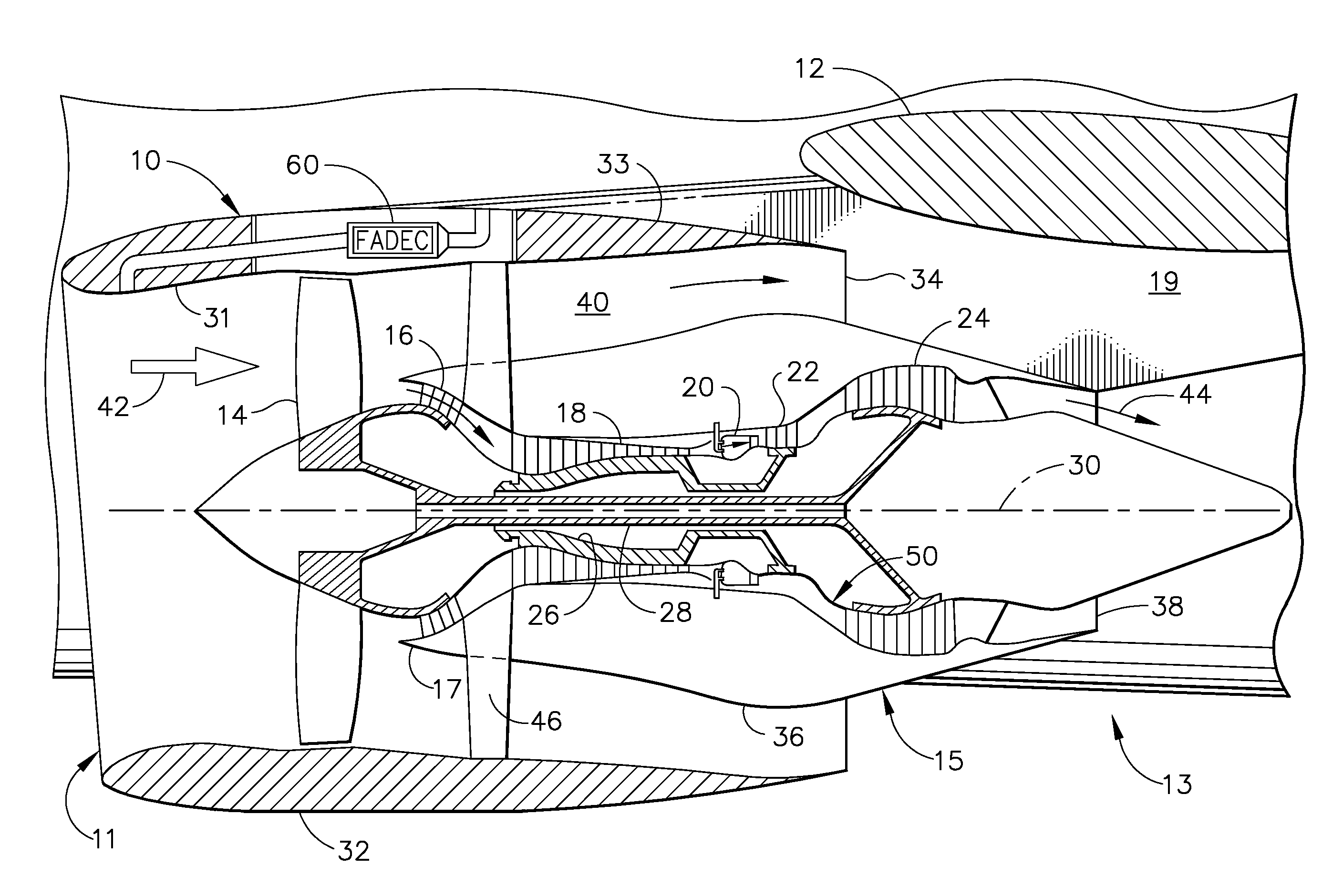
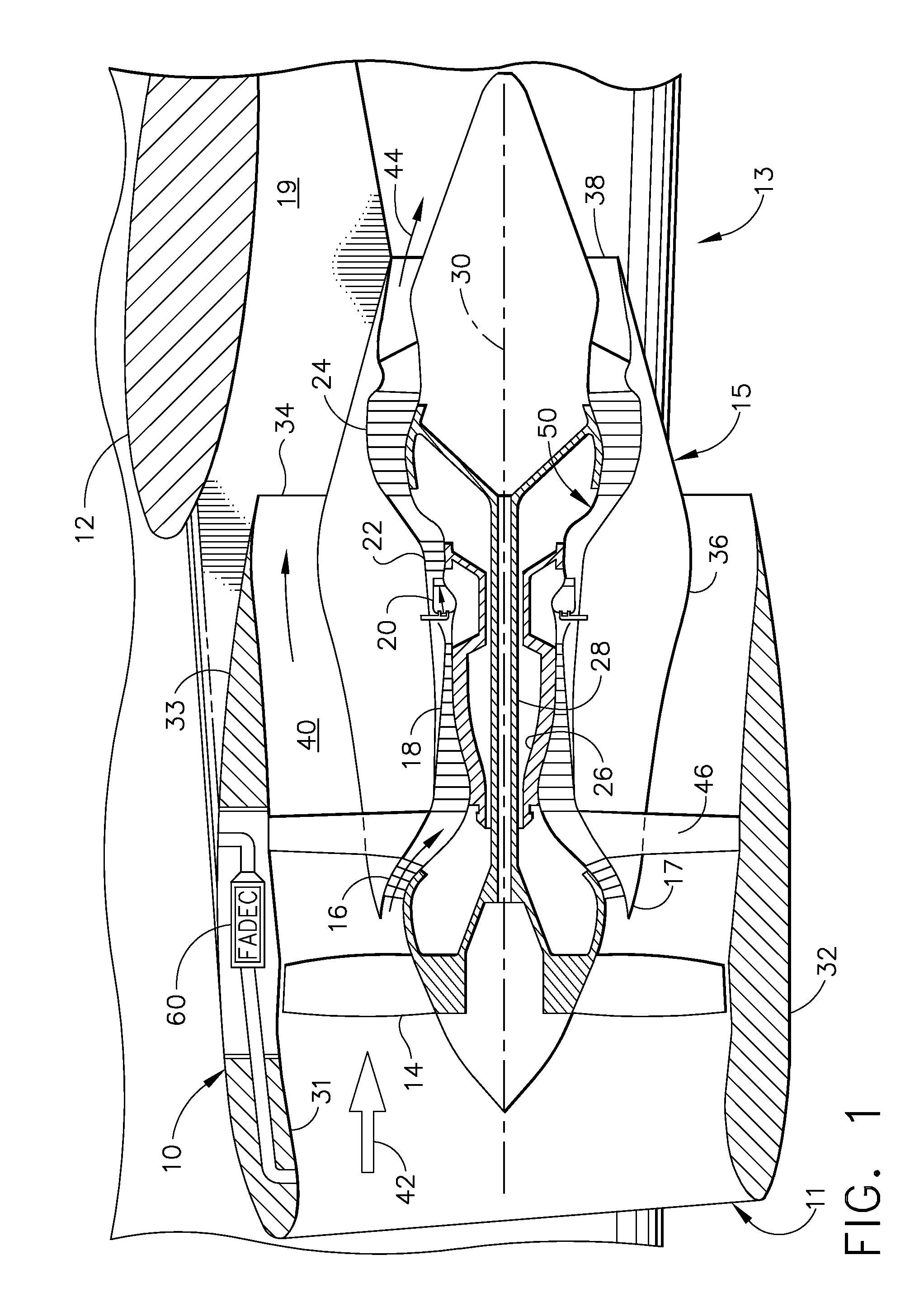
[0023]FIG. 1 is a cross-sectional schematic illustration of an exemplary gas turbine engine assembly 10 having a longitudinal axis 30. Gas turbine engine assembly 10 includes a fan assembly 14 and a core gas turbine engine 15. Core gas turbine engine 15 includes a high pressure compressor 18, a combustor 20, and a high pressure turbine 22. In the exemplary embodiment, gas turbine engine assembly 10 also includes a low pressure turbine 24, and a multi-stage booster compressor 16, and a splitter 17 that substantially circumscribes booster 16.

[0024]Fan assembly 14 includes an array of fan blades extending radially outward from a rotor disk, the forward portion of which is enclosed by a streamlined spinner. Gas turbine engine assembly 10 has an intake side 11 and an exhaust side 13. Fan as...


PUM


Abstract

A system for cooling a gas turbine engine control component comprises a control component, at least one duct in fluid communication with the component and the atmosphere, and a valve assembly located with the duct for modulating airflow to the component. A method for cooling a gas turbine engine control component comprises the steps of: a) providing a system for cooling the component, the system comprising at least one duct in fluid communication with the component and the atmosphere and a valve assembly located with the duct for modulating airflow to the component; b) exposing the system to a first condition where cooling of the component is required; c) opening the valve assembly in response to the first condition; d) exposing the system to a second condition where cooling of the component is not required; and e) closing the valve assembly in response to the second condition.

Description

CROSS REFERENCE TO RELATED APPLICATION[0001]This application is a continuation-in-part of U.S. patent application Ser. No. 11 / 967,904 filed Dec. 31, 2007.BACKGROUND OF THE INVENTION[0002]The technology described herein relates generally to gas turbine engines, and more particularly, to a system and method for cooling engine control components for such engines.[0003]At least one known gas turbine engine assembly includes a fan assembly that is mounted upstream from a core gas turbine engine. During operation, a portion of the airflow discharged from the fan assembly is channeled downstream to the core gas turbine engine wherein the airflow is further compressed. The compressed airflow is then channeled into a combustor, mixed with fuel, and ignited to generate hot combustion gases. The combustion gases are then channeled to a turbine, which extracts energy from the combustion gases for powering the compressor, as well as producing useful work to propel an aircraft in flight. The othe...

Claims


Application Information

Patent Timeline
IPC IPC(8): F01D5/08
CPCF01D25/12F02C7/12Y02T50/675H05K7/20136Y02T50/672F05D2270/54Y02T50/60
Inventor DIAZ, CARLOSLABORIE, DANIELLEIVA, ORLY
Owner GENERAL ELECTRIC CO
Why Eureka
Try Eureka