Chair-Type Massaging Apparatus, Massaging Apparatus, Control Device of Chair-Type Massaging Apparatus And Remote Control Device For Chair-Type Massaging Apparatus

Inactive Publication Date: 2009-07-09
FAMILY INADA
View PDF3 Cites 56 Cited by
  • Summary
  • Abstract
  • Description
  • Claims
  • Application Information

AI Technical Summary

Benefits of technology

[0078]In accordance with the present invention, it is possible to provide a chair-type massaging apparatus, a massaging apparatus, a control device of the chair-type massaging apparatus, and a remote control device for the chair-type massaging apparatus, which are user friendly.
[0079]To be specific, it is possible to provide a massaging apparatus that is configured to move a massaging portion that stimulates a user according to a displacement amount of the control device so that the user does not feel discomfort in operating the control device that may be caused by a delay of an operation of the massaging portion.
[0080]It is possible to provide a control device that enables a chair-type massaging apparatus to carry out various massage operations in such a manner that a massage operation is selected by selecting a massage operation switch and a massage posi

Problems solved by technology

When there is a directional mismatch between the operation of the control device by the user and the movement of the massaging element, the user may in some cases feel discomfort and feel difficulty in operating the control device to move the massaging element to a desired position.
In the chair-type massaging apparatus disclosed in the above identified U.S. Pat. No. 2,566,275, when the user tilts the control device, only a signal indicating the tilting direction is output from a simple ON/OFF switch, causing the user to feel discomfort in operating the control device.
However, if the chair-type massaging apparatus is configured in such a manner that the displacement amount of the control device is proportional to the displacement amount of the massaging element, then the massaging element may be displaced with a delay with respect to the displacement of the control device, because the massaging element is typically mechanically driven by a motor, gears, etc.
In the joystick control device, since the desired operation mode is thus selected from the preset operation modes, choices are limited.
In the joystick control device disclosed in Japanese Laid-Open Patent Application Publication No. 2004-16428, since the selectable operation modes are limited as described above, the massage operation for the individual part is unable to be selected.
If the operation mode is increased

Method used


Image

  • Chair-Type Massaging Apparatus, Massaging Apparatus, Control Device of Chair-Type Massaging Apparatus And Remote Control Device For Chair-Type Massaging Apparatus
  • Chair-Type Massaging Apparatus, Massaging Apparatus, Control Device of Chair-Type Massaging Apparatus And Remote Control Device For Chair-Type Massaging Apparatus
  • Chair-Type Massaging Apparatus, Massaging Apparatus, Control Device of Chair-Type Massaging Apparatus And Remote Control Device For Chair-Type Massaging Apparatus

Examples


first embodiment

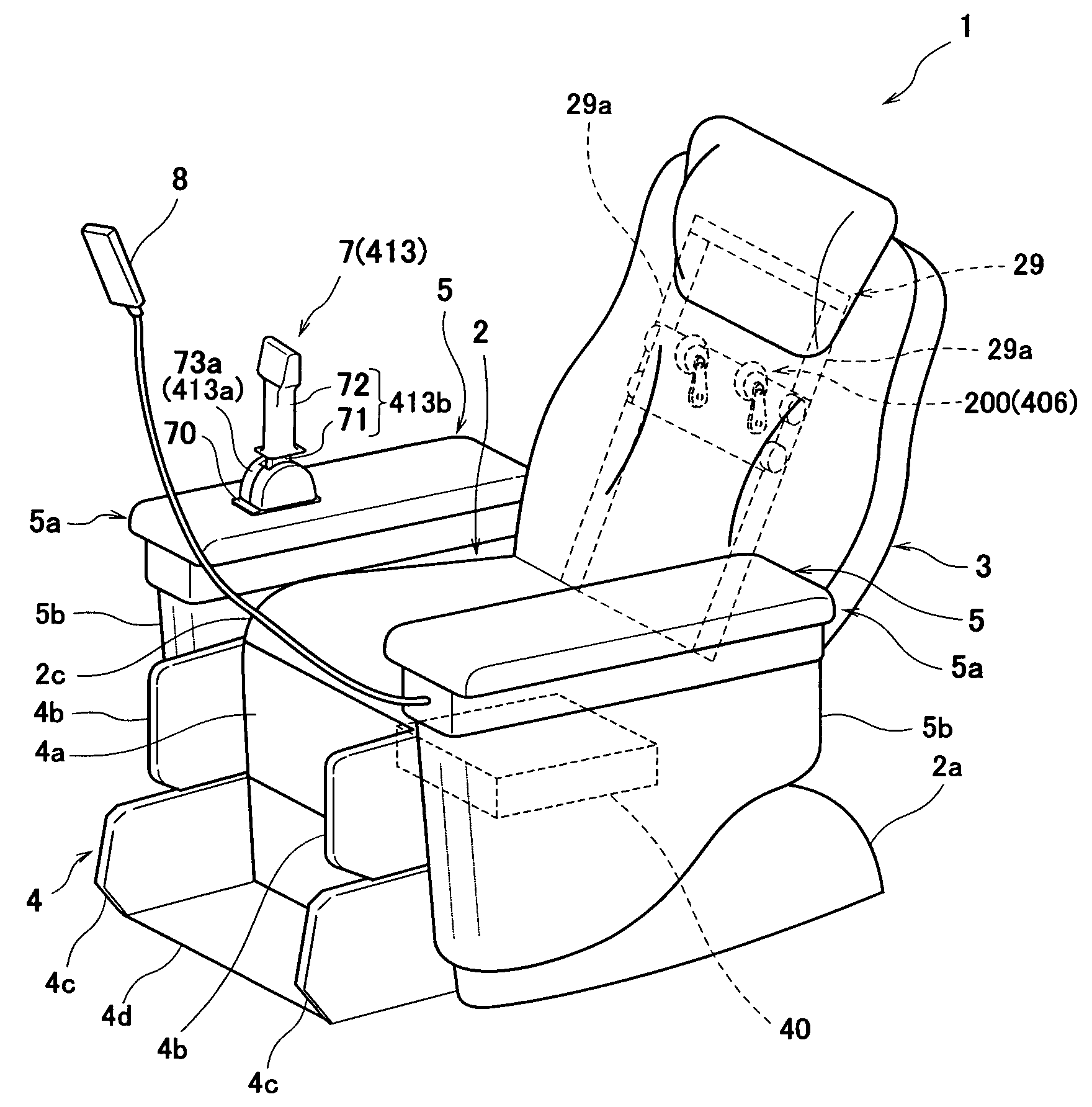
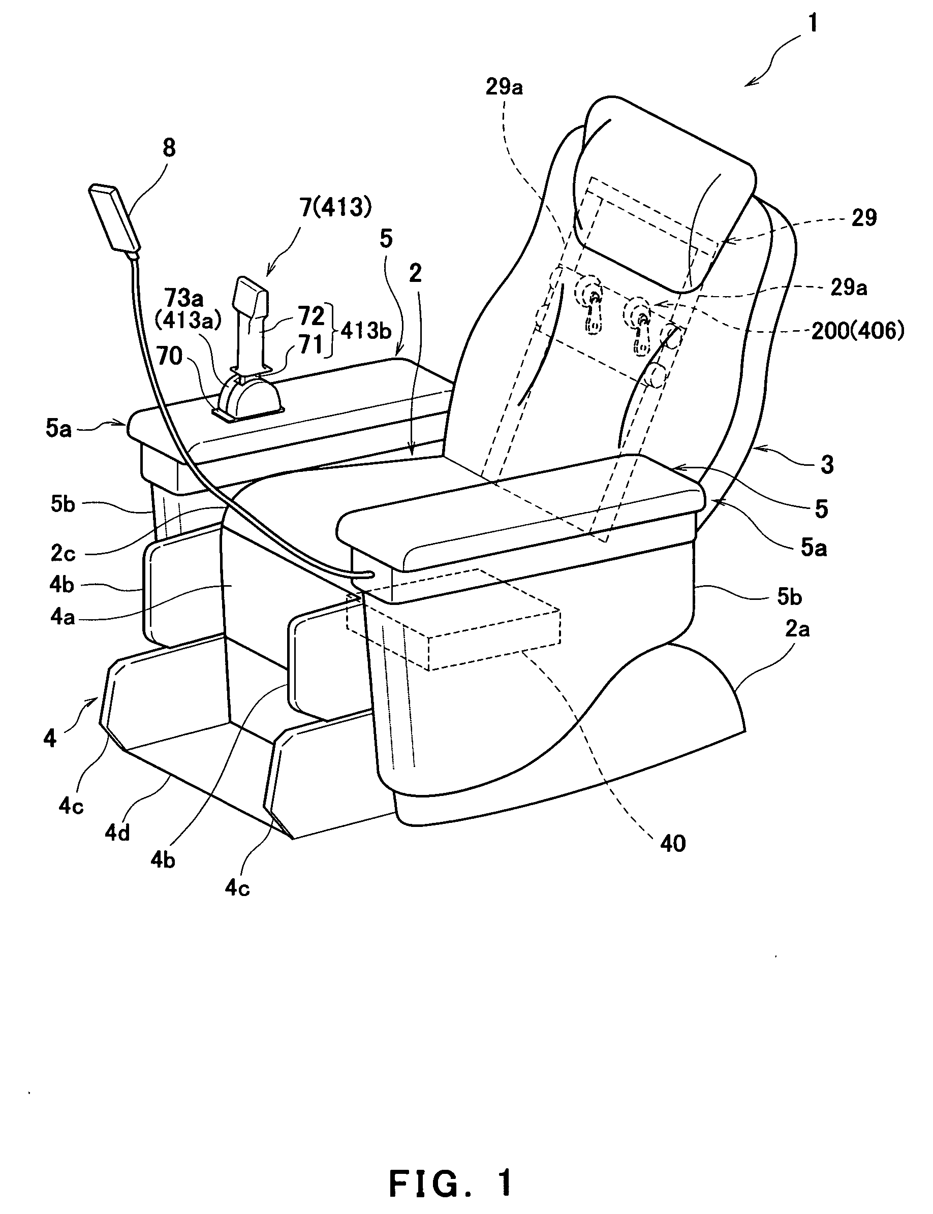
[0157]FIG. 1 is a perspective view showing a construction of an entire chair-type massaging apparatus according to embodiments of the present invention. A chair-type massaging apparatus 1 mainly comprises a seat portion 2, a back rest 3, a foot rest 4 and arm rests 5. The seat portion 2 is constructed such that a cushion portion 2c whose upper surface is substantially flat for use as a seat surface is disposed on an upper region of a base (not shown) having leg portions 2a on both sides under the base (left leg portion 2a is illustrated in FIG. 1). The cushion portion 2c is formed in such a manner that an internal material (not shown) such as urethane foam, sponge, or foamed polystyrene is provided over an upper surface of the base and is covered with an outer material (cover) formed of a raised-fiber tricot made of polyester, artificial leather, or natural leather, etc.

[0158]The foot rest 4 is pivotally attached at an upper end thereof to a front side of an upper region of the seat...

embodiment 2

[0248]FIG. 16 is a functional block diagram showing a second embodiment of the chair-type massaging apparatus 1 illustrated in FIG. 1. In FIG. 16, a massaging system 406, a controller 411, a remote control device 412, and a control device 413, which respectively correspond to the massaging system 200, the controller 40, the remote control device 8, and the control device 7 (or the control device 300) are illustrated, and other functions of the foot rest 4 or the like having the air bags are omitted. Since the massaging system 406, the remote control device 412, and the control device 413 are identical in construction to the massaging system 200, the remote control device 8, and the control device 7 (or the control device 300) described in the first embodiment, except for a case specifically illustrated, they will not be further described.

[0249]As shown in FIG. 16, the controller 411 of the chair-type massaging apparatus 1 mainly includes, a CPU 420, a RAM 421, a ROM 422, and an inpu...

embodiment 3

[0281]Now, another embodiment of the present invention will be described.

[0282]FIG. 24 is a perspective view showing a construction of an entire chair-type massaging apparatus according to a third embodiment of the present invention. FIG. 25 is a side view schematically showing a moving state of a massaging system of the chair-type massaging apparatus of FIG. 24. In this embodiment, a joystick will be described as an example of an operation member of a control device. In the third embodiment, the term “forward and backward and rightward and leftward” means the directions from the perspective of the user seated in the chair-type massaging apparatus 501. For example, the front side refers to forward of the user, the left side refers to leftward of the user, and the right side refers to rightward of the user.

[0283]As shown in FIG. 24, the chair-type massaging apparatus 501 of the third embodiment mainly comprises a seat portion 502, a back rest 503, a foot rest (leg rest) 504, and arm ...


PUM


Abstract

A chair-type massaging apparatus of the present invention, including a massaging element that is mounted in a back rest configured to support a back of a user and is configured to be movable in a substantially forward and backward direction to apply stimulation to the back, a control device that includes a grip that is tilted by the user to be displaceable from a predetermined neutral position in the forward and backward direction substantially corresponding with the direction in which the massaging element moves and is configured to output a signal indicating a displacement of the grip, and a controller configured to, based on the signal from the control device, execute control to move the massaging element in a direction substantially corresponding with a direction in which the grip is operated to move.

Description

TECHNICAL FIELD[0001]The present invention relates to a chair-type massaging apparatus and a massaging apparatus that are configured to massage bodies of users, and various control devices equipped in these massaging apparatuses. More particularly, the present invention relates to a chair-type massaging apparatus and a massaging apparatus that are configured to massage bodies of users seated therein by operating a control device without mental effort or feeling discomfort, and various control devices equipped in these massaging apparatuses.BACKGROUND ART[0002]Conventional massaging apparatuses that are capable of massaging bodies of users include a massaging element configured to stimulate the bodies of the users, and a control device operated by the users to change a position of the massaging element. One example of the conventional massaging apparatuses is a chair-type massaging apparatus disclosed in a Japanese Patent No. 2566275. This chair-type massaging apparatus includes a ve...

Claims


Application Information

Patent Timeline
IPC IPC(8): A61H7/00
CPCA61H7/001A61H15/0078A61H2201/0149A61H2205/10A61H2203/0431A61H2205/062A61H2205/081A61H2201/1669A61H7/00A61H15/00A61H23/02
Inventor FUKUYAMA, YOSHIFUMINAGAMITSU, TOMOKIGONDAI, AKIHIKOTAKATSUKA, KEISUKEFUKUDA, TOMOHARUKATO, MITSUNORI
Owner FAMILY INADA
Why Eureka
Try Eureka