Emergency stretcher

Active Publication Date: 2009-07-16
STRYKER CORP
View PDF13 Cites 11 Cited by
  • Summary
  • Abstract
  • Description
  • Claims
  • Application Information

AI Technical Summary

Benefits of technology

[0005]Accordingly, the emergency stretcher of the present invention includes a support frame with the handling capability of prior support frames, but with increased stiffness in the raised position to reduce wobbling or play of the litter surface that may occur on prior ambulance stretchers. Further, when it its compact, folded configuration, the patient support is locked relative to the base, which elimina

Problems solved by technology

Because of the collapsible nature of the support legs, when the stretcher is in its folded, compact configuration there may be wobble or end-to-end movement that is

Method used


Image

  • Emergency stretcher
  • Emergency stretcher
  • Emergency stretcher

Examples


Example

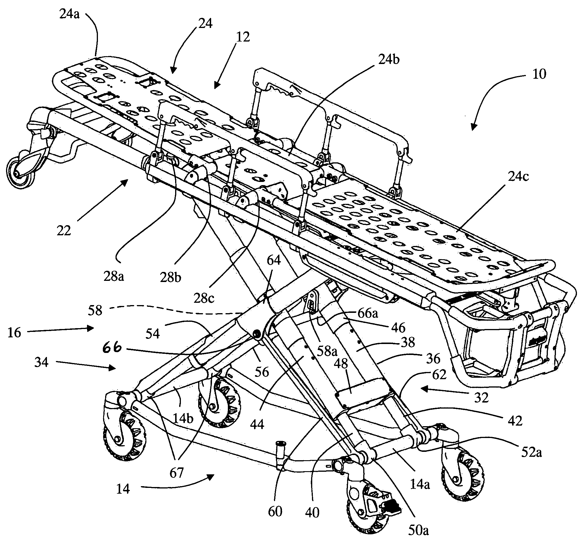
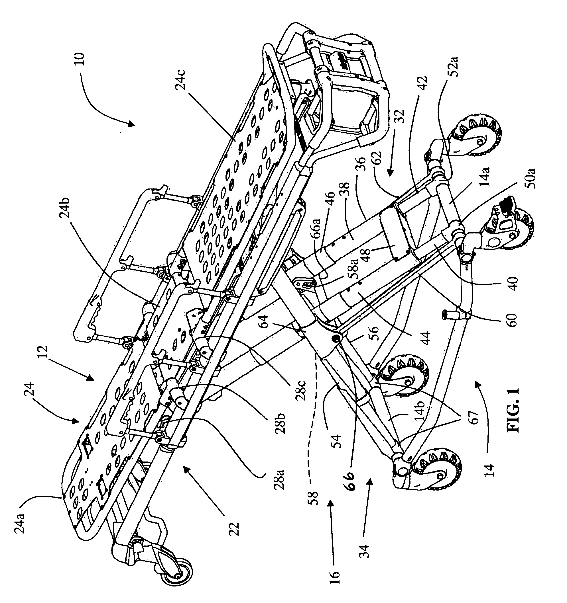
[0036]Referring to FIG. 1, the numeral 10 generally designates an emergency stretcher or cot of the present invention. Emergency stretcher 10 includes a patient support 12 and a base 14, with a plurality of bearings, such as wheels or castors. Patient support 12 is supported on base 14 by a support frame 16, which is configured to raise or lower the base or patient support relative to the other so that the stretcher can be rearranged between a more compact configuration for loading into an emergency vehicle, such as an ambulance, and a configuration for use in transporting a patient across a ground surface, as will be more fully described below. As will more fully described below in reference to FIGS. 12-15, stretcher 10 may incorporate a mechanical link between the patient support and the base, which reduces, if not, eliminates “base sag”.

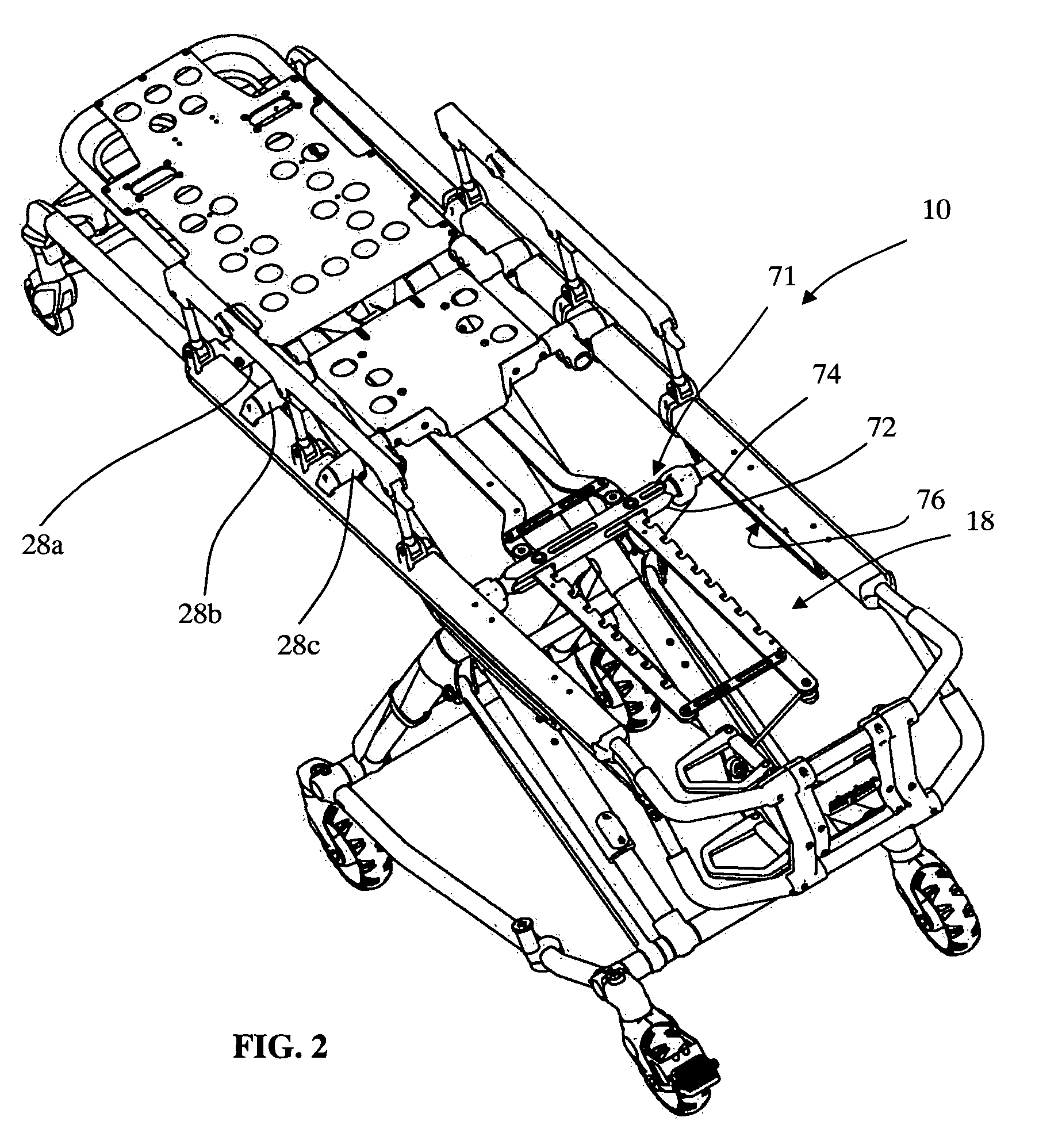
[0037]To lock the vertical height of support frame 16, stretcher 10 incorporates a locking mechanism 18 (FIG. 2), which also may provide a height...


PUM


Abstract

A stretcher includes a patient support, a base, and a plurality of support members, which supports the patient support relative to the base. The support members are adapted and arranged to raise or lower the base relative to the patient support. The stretcher also includes a releasable locking link between the patient support and a fixable point at the base.

Description

[0001]This application claims the benefit of provisional patent application entitled EMERGENCY STRETCHER, Ser. No. 61 / 020,884, filed Jan. 14, 2008, which is hereby incorporated by reference in its entirety herein.TECHNICAL FIELD AND BACKGROUND OF THE INVENTION[0002]The present invention relates to an emergency stretcher or cot and, more particularly, to an emergency stretcher that eliminates “base sag” and remains in its compact, folded configuration, which results in the cot being easier to load or unload from an emergency transport vehicle.[0003]When a stretcher is unloaded, for example from an ambulance, it is often desirable to allow the base of the stretcher to be quickly released and lowered from its compact configuration in the ambulance to a ground engaging position spaced further from the patient support or litter of the stretcher. This release is referred to as a “hot-drop” function, which allows a single emergency medical technician (EMT) to remove a stretcher out of the ...

Claims


Application Information

Patent Timeline
IPC IPC(8): A47B9/00A47B1/00A61G7/10
CPCA61G1/0567A61G2007/0509A61G2203/723A61G1/0262A61G1/0212A61G1/0237A61G7/0509
Inventor NAHAVANDI, KUROSHKNIPFEL, STEVELAMBARTH, CLIFF
Owner STRYKER CORP
Why Eureka
Try Eureka