Electrically driven brake booster and master cylinder

a brake booster and master cylinder technology, applied in the direction of braking systems, rotary clutches, fluid couplings, etc., can solve the problems of difficult increase, low fluid pressure in the primary pressure chamber, so as to achieve easy control

Active Publication Date: 2009-07-16
HITACHI LTD
View PDF2 Cites 13 Cited by
  • Summary
  • Abstract
  • Description
  • Claims
  • Application Information

AI Technical Summary

Benefits of technology

[0004]The present invention has been contrived in consideration of the above-mentioned conventional problem, and an object thereof is to provide an electric booster and a master cylinder in which, even under circumstances in which the fluid pressure in the primary pressure chamber of the tandem master cylinder is difficult to be increased, the fluid pressure in the secondary pressure chamber can be easily controlled.

Problems solved by technology

However, in the electric booster disclosed in Japanese Patent Public Disclosure No. 2007-191133, when the axial member moves forward under circumstances in which the fluid pressure in the primary pressure chamber of the tandem master cylinder is difficult to be increased for some reason, for example, bubble presence in the fluid, the fluid pressure in the primary pressure chamber remains low while the fluid pressure in the secondary pressure chamber is increased by a forward movement of the cylindrical member.
As a result, a fluid pressure reactive force cannot be transmitted to the axial member (brake pedal).
In this case, a driver continues the pedal operation, with a still weak pedal pressing force, i.e., without feeling a reactive force of the brake fluid pressure, whereby it becomes difficult to control the fluid pressure in the secondary pressure chamber.

Method used


Image

  • Electrically driven brake booster and master cylinder
  • Electrically driven brake booster and master cylinder
  • Electrically driven brake booster and master cylinder

Examples


first embodiment

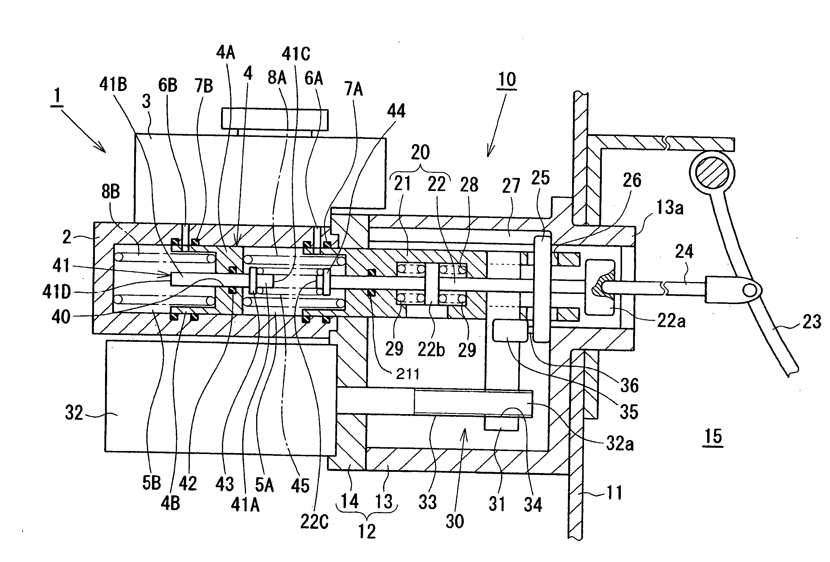
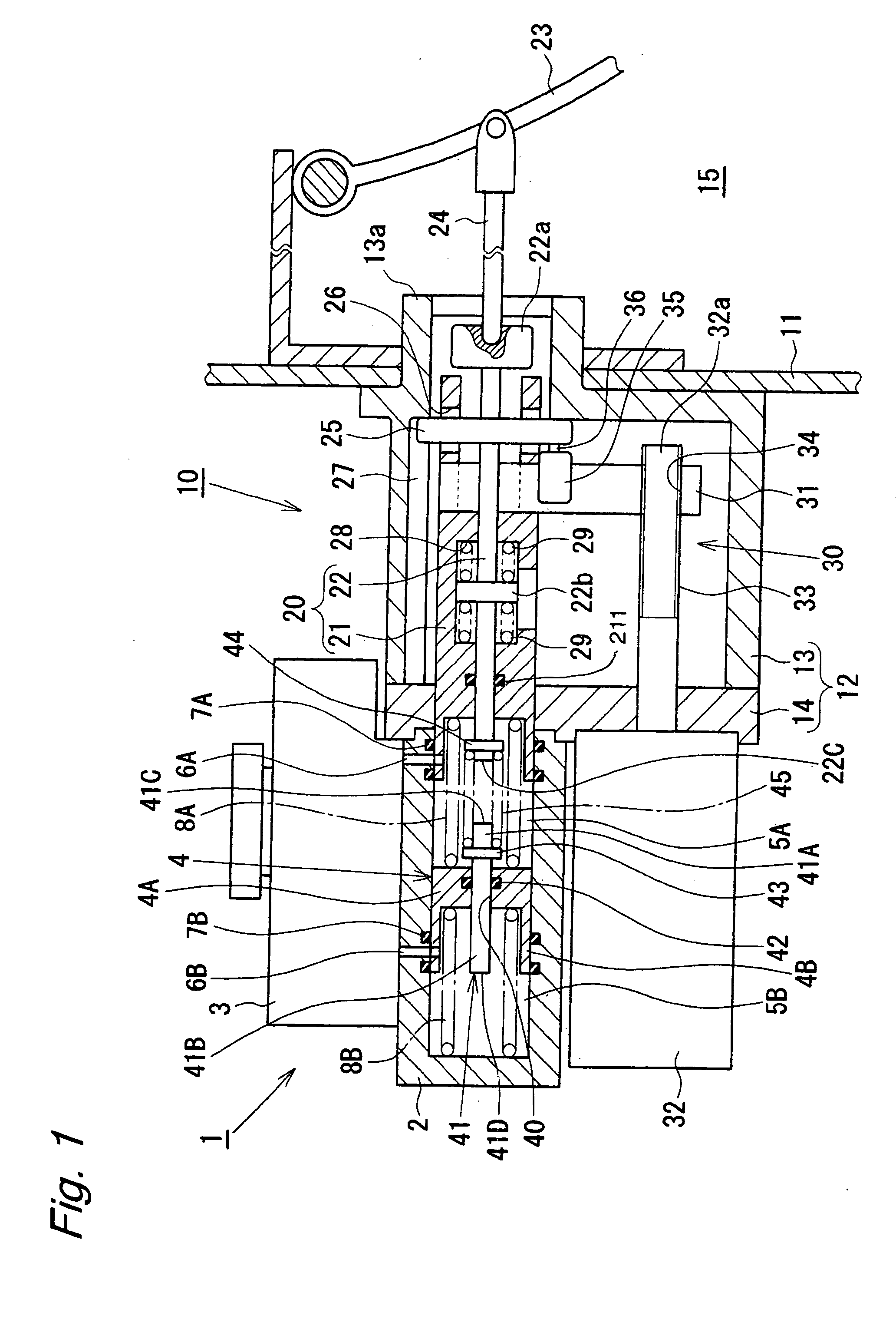
[0012]FIG. 1 shows an electric booster according to the present invention. An electric booster 10 comprises a booster case 12 having one end fixed to a vehicle compartment wall 11 separating an engine room and a vehicle compartment, and the other end coupled to a tandem master cylinder 1 which will be described later. The booster case 12 comprises a bottomed case body 13 and a cover 14 covering an opening of the case body 13. While the case body 13 is fixed to the vehicle compartment front wall 11, the tandem master cylinder 1 is coupled to the cover 14 of the case body 13. Further, a cylindrical boss portion 13a is formed on a bottom plate portion of the case body 13, and the boss portion 13a extends into a vehicle compartment 15 through the vehicle compartment wall 11. The booster case 12 contains a piston assembly 20 and an electric actuator 30. The piston assembly 20 also serves as a primary piston of the tandem master cylinder 1, as will be described later. The electric actuato...

third embodiment

[0035]FIGS. 3 and 4 show the present invention. The third embodiment is characterized in that it employs, instead of the rod member 41 employed as an example of a transmission member in the first and second embodiments, an elastic member as another example of a transmission member. In the third embodiment, an electric booster 110 comprises a casing 111 having one end fixed to a partition wall W separating an engine room R1 and a vehicle compartment R2, and the other end coupled to a tandem master cylinder 101, which will be described later. Hereinafter, for convenience of description, the side of the engine room R1 is referred to as “front side”, and the side of the vehicle compartment R2 is referred to as “rear side”. The casing 111 comprises a cylindrical casing body 112, and a cover 113 attached to the rear side end of the casing body 112 by a bolt. A stepped wall 112a is integrally formed at the front end of the casing body 112, and the tandem master cylinder 101 is fixedly coup...

fourth embodiment

[0058]The characteristic features of the fourth embodiment will now be described in detail with reference to FIG. 5. As shown in FIG. 5, a circular groove 204a sharing a common radial center with a secondary piston 204 is formed on the base end side of the secondary piston 204, and a peripheral wall 204b is formed around the groove 204a. A step groove portion 204c is formed on the opening side of the peripheral wall 204b so as to have a larger diameter than that of the bottom of the groove 204a. In the groove 204a, a rubber reaction disk 161, which corresponds to an elastic member, is disposed so as to abut against the bottom of the groove 204a and the inner circumferential surface of the peripheral wall 204b. A ring-shaped push piece 262 is disposed in the groove 204a so as to abut against the opposite surface of the reaction disk 161 from the surface abutting against bottom of the groove 204a, and so as to be movable on the inner circumferential surface of the peripheral wall 104b...


PUM


Abstract

An electric booster according to the present invention comprises a booster piston disposed around an input piston so as to movable relative to the input piston. The booster piston and input piston also serve as a primacy piston of a tandem master cylinder. A brake fluid pressure is generated in the tandem master cylinder by an input thrust force provided from a brake pedal to the input piston and a booster thrust force provided from the electronic actuator to the booster piston. In this electric booster, a slide hole is formed through the secondary piston of the tamed master cylinder in the axial direction therefore, and a rod member is slidably disposed through the slide hole. When the fluid pressure is not increased in the primary pressure chamber, due to the fluid pressure in the secondary pressure chamber, the rod member comes to abut against the input piston, and a reactive force in the secondary pressure chamber is returned to the brake pedal.

Description

BACKGROUND OF THE INVENTION[0001]The present invention relates to a booster and a master cylinder for use in a brake system of a vehicle.[0002]Examples of conventional electric boosters include the electric booster disclosed in Japanese Patent Public Disclosure No. 2007-191133. This electric booster comprises an axial member adapted to move forward and backward in response to an operation of a brake pedal, a cylindrical member disposed around the axial member so as to be movable relative to the axial member, and an electric actuator operable to cause a forward / backward movement of the cylindrical member. In this electric booster, the axial member and the cylindrical member face a primary pressure chamber of a tandem master cylinder, and a brake fluid pressure is generated in the tandem master cylinder by an input thrust force provided from the brake pedal to the axial member, and a booster thrust force provided from the electric actuator to the cylindrical member.[0003]However, in t...

Claims


Application Information

Patent Timeline
Patent Type & Authority Applications(United States)
IPC IPC(8): B60T13/74F16D65/14
CPCB60T13/745B60T11/20
Inventor IKEDA, JUNICHIOIKAWA, HIROTAKAOHNO, TAKAYUKI
Owner HITACHI LTD
Why Eureka
Try Eureka