Touch detecting device of keyboard instrument

a keyboard instrument and detecting device technology, applied in the field of keyboard instruments, can solve the problems of inability to accurately detect the key depression speed, the inability to detect the key depression timing or the key release timing accurately, and the reduction of the amount of light received by the light receiving part, so as to reliably eliminate the adverse influence of the reflected light and reduce the amount of reflected light

Active Publication Date: 2009-07-16
KAWAI MUSICAL INSTR MFG CO
View PDF10 Cites 17 Cited by
  • Summary
  • Abstract
  • Description
  • Claims
  • Application Information

AI Technical Summary

Benefits of technology

[0013]According to the present invention, adjacent two of the optical sensors are arranged such that the light emitting part of one of the two and the light receiving part of the other of the two are disposed adjacent to each other on the same side of the pivotal path of the shutter. For this reason, even when light beams emitted from the light emitting parts are divergent, light from the light emitting part of one of the optical sensors reaches only the light receiving part of the optical sensor and the light emitting part of the other optical sensor, which is adjacent to the light receiving part, but never reaches the light receiving part of the other optical sensor. Therefore, when only one of the optical paths of the respective optical sensors is closed by the shutter, the associated light receiving part does not receive light from the light emitting part of the other optical sensor, so that it is possible to cause switching timing between presence and absence of light received by the light receiving part to coincide with timing in which the optical path is actually opened or closed by the shutter. Therefore, even when the light beams emitted from the light emitting parts are divergent, it is possible to detect touch information of a key with high accuracy without being adversely affected by light from the other optical sensors.
[0014]For the same reason, it is possible to cause timing of switching between presence and absence of light received by the light receiving part to coincide with timing in which the optical path is actually opened or closed by the shutter, irrespective of the position of passage of the shutter between the light emitting part and the light receiving part of the optical sensor. Further, even when the distance between the optical sensors is reduced, detection accuracy is not affected, so that by reducing the distance, it is possible to enhance the mounting density of the optical sensors, and due to reduced length of a section for detecting the key depression speed, detect a key depression speed immediately before striking of the string, which is important as key depression information, with high accuracy, for example. Furthermore, even when light emission intensity is set to a high level, detection accuracy is not affected, so that by setting the light emission intensity to a high level, it is possible to stabilize the outputs from the respective optical sensors to thereby detect touch information of the key with further enhanced accuracy.
[0016]In the touch detecting device according to claim 1, in a state where the optical path of one of the optical sensors is closed by the shutter, light from the light emitting part of the other optical sensor can be reflected by the shutter to reach the light receiving part of the one sensor. According to the present invention, since the shutter is configured as above, when light from the other optical sensor is reflected by the shutter, the amount of the reflected light is reduced by the shutter. Therefore, even when the reflected light has reached the light receiving part of the one sensor, it is possible to reliably eliminate adverse influence of the reflected light.

Problems solved by technology

This makes it impossible to detect key depression timing or key release timing with accuracy.
Thus, the key depression speed cannot be accurately detected.
In this case, however, the total amount of light received by the light receiving part is reduced, and hence, even though a light receiving part is in the light receiving state, the amount of light received by the light receiving part sometimes becomes lower than a predetermined level, which causes instability of the detection signal and thereby considerably degrades the accuracy of detection of the key depression and release timings and that of detection of the key depression speed.

Method used


Image

  • Touch detecting device of keyboard instrument
  • Touch detecting device of keyboard instrument
  • Touch detecting device of keyboard instrument

Examples


first embodiment

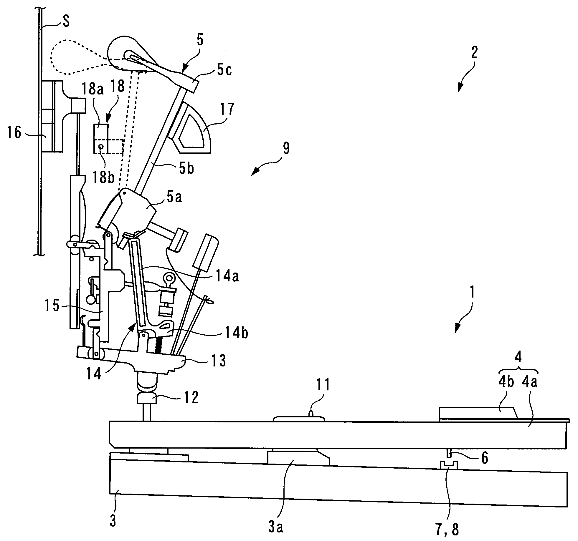
[0033]The invention will now be described in detail with reference to the drawings showing preferred embodiments thereof. FIG. 1 shows a upright silent piano 2 (keyboard instrument) to which is applied a touch detecting device 1 according to the present invention. In the following description, a player's side of the silent piano (right side as viewed in FIG. 1) will be referred to as “front”, and a remote side (left side as viewed in FIG. 1) from the player's side as “rear”. Further, the player's left side will be referred to as “left”, and the player's right side as “right”.

[0034]As shown in FIG. 1, the silent piano 2 is comprised of a plurality of (e.g. eighty-eight) keys 4 (only one of which is shown) mounted on a keybed 3 and including white keys 4a and black keys 4b, an action 9 provided above the rear part of each key 4, a hammer 5 provided for the key 4 to strike an associated string S, and a musical tone generator 10 (see FIG. 7) for electronically generating performance sou...

second embodiment

[0092]Further, although in the second embodiment, the first to third detection signals S11 to S13 are delivered to the single sensor scan circuit 22, this is not limitative. For example, two sensor scan circuits may be separately provided such that the detection signal S11 from the first optical sensor 42 disposed in the vicinity of the key 4 can be delivered to one of the sensor scan circuits, and the second and third detection signals S12 and S13 from the respective second and third optical sensors 43 and 44 disposed in the vicinity of the hammer 5 can be delivered to the other sensor scan circuit. In this case, it is possible to easily connect the optical sensors to the respective associated sensor scan circuits, and increase the degree of freedom in layout of the optical sensors.

[0093]Further, although in the embodiments, the present invention is applied to the upright silent piano 2, by way of example, this is not limitative, but the present invention can be applied to a grand-...


PUM


Abstract

There is provided a touch detecting device of a keyboard instrument, which makes it possible not only to enhance the mounting density of a plurality of optical sensors, but also to detect touch information of a key with high accuracy without being affected by light from the other optical sensors. The touch detecting device comprises a shutter 6 that moves in accordance with pivotal motion of a key 4, a plurality of optical sensors 7 and 8 that are provided close to a pivotal path of the shutter 6 and have respective light emitting parts 7a and 8a and respective light receiving parts 7b and 8b for receiving light emitted from the light emitting parts, on respective opposite sides of the pivotal path, and touch information detecting means 23 for detecting, as the key 4 pivotally moves, the touch information based on presence or absence of light received by the light receiving parts of the optical sensors 7 and 8 in accordance with opening or closing of optical paths of light from the light emitting parts of the optical sensors 7 and 8, by the shutter 6. Adjacent two of the optical sensors 7 and 8 are arranged such that the light emitting part of one of the two and the light receiving part of the other of the two disposed adjacent to each other on the same side of the pivotal path of the shutter 6.

Description

FIELD OF THE INVENTION[0001]The present invention relates to a touch detecting device of a keyboard instrument, which is applied to an electronic keyboard instrument, such as an electronic piano, and a hybrid piano, such as a silent piano or an automatic performance piano, and is configured to detect touch information containing key depression information.BACKGROUND ART[0002]As a conventional touch detecting device of a keyboard instrument, there has been known one disclosed e.g. in Patent Literature 1. This keyboard instrument is an upright automatic performance piano, and is comprised of pivotally movable keys (not shown) and hammers 63 each of which pivotally moves in accordance with depression of an associated key to strike an associated string 62, as shown in FIG. 14. As shown in FIG. 14, the touch detecting device 61 includes a shutter 64 attached to an associated one of the hammers 63, and first to third sensors 65 to 67. The shutter 64 is in the form of a plate shape, and ex...

Claims


Application Information

Patent Timeline
Patent Type & Authority Applications(United States)
IPC IPC(8): G10H1/34
CPCG10G3/04G10H1/34G10H2220/411G10H2220/305G10H1/344G10B3/12G10F1/02G10H1/057
Inventor HIRANO, TETSUYA
Owner KAWAI MUSICAL INSTR MFG CO
Why Eureka
Try Eureka