Pneumatic Tire

a technology of pneumatic tires and tyres, which is applied in the field of pneumatic tires, can solve the problems of deteriorating the traveling performance on the iced road surface, enhancing not suggesting solutions for solving the unevenness of the ground contact pressure, so as to reduce the rigidity of the region, prevent the local lowering of the rigidity of the block, and enhance the traveling performance

Active Publication Date: 2009-07-16
TOYO TIRE & RUBBER CO LTD
View PDF2 Cites 2 Cited by
  • Summary
  • Abstract
  • Description
  • Claims
  • Application Information

AI Technical Summary

Benefits of technology

[0010]The present invention is made by taking the above actual condition into consideration, and an object of the present invention is to provide a pneumatic tire which can uniformize a ground contact pressure within a block so as to enhance a traveling performance on an iced road surface, without locally lowering too much a rigidity of the block.
[0012]In the pneumatic tire in accordance with the present invention, since the sipe is formed on the wall surface of the block, it is possible to lower the rigidity of the region close to the wall surface. Accordingly, it is possible to uniformize the ground contact pressure within the block by dispersing the pressure in the region in which the ground contact pressure tends to be particularly high. Further, since the upper surface sipe, the first wall surface sipe and the second wall surface sipe extend in the directions intersecting each other, they are not arranged within the same plane, and it is possible to prevent the rigidity of the block from locally lowering too much. As mentioned above, in accordance with the present invention, it is possible to uniformize the ground contact pressure within the block so as to enhance the traveling performance on the iced road surface without locally lowering too much the rigidity of the block.
[0013]In the above structure, it is preferable that the first wall surface sipe and the second wall surface sipe are terminated within the wall surface without being open to a ridge line of the block. Accordingly, it is possible to prevent the rigidity from lowering too much in the ridge line portion of the block, and it is possible to preferably secure the steering stability performance or the like. In this case, the ridge line of the block includes a ridge line between the upper surface of the block and each of the wall surfaces, and a ridge line between the wall surfaces of the blocks.
[0014]In the above structure, it is preferable that the upper surface sipe is constituted by a closed sipe. In accordance with the structure mentioned above, since it is possible to secure the length of the wall surface sipe in the wall surface positioned in the longitudinal direction of the upper surface sipe, it is possible to easily lower the rigidity of the region close to the wall surface.
[0015]In the above structure, it is preferable that the block is provided with an upper layer portion arranged in an upper surface side, and a lower layer portion made of a harder rubber than the upper layer portion and arranged in an inner side in the tire diametrical direction of the upper layer portion, and the number of at least one of the first wall surface sipe and the second wall surface sipe is made more in the lower layer portion than the upper layer portion. In accordance with the structure mentioned above, it is possible to make the rigidity balance between the upper layer portion and the lower layer portion of the block favorable so as to enhance the uniformity of the ground contact pressure within the block, while lowering the ground contact pressure in the region in which the ground contact pressure tends to become particularly high.
[0016]In the above structure, it is preferable that the block is provided with an upper layer portion arranged in an upper surface side, and a lower layer portion made of a harder rubber than the upper layer portion and arranged in an inner side in the tire diametrical direction of the upper layer portion, and the at least one of the first wall surface sipe and the second wall surface sipe is formed by a waveform sipe and the wave number of the wall surface sipe is set more in the lower layer portion than the upper layer portion. In accordance with the structure mentioned above, it is possible to make the rigidity balance between the upper layer portion and the lower layer portion of the block favorable so as to enhance the uniformity of the ground contact pressure within the block, while lowering the ground contact pressure in the region in which the ground contact pressure tends to become particularly high.

Problems solved by technology

Further, as a result of repeatedly making a study, it is found that a region in which the ground contact pressure becomes particularly high exists in the vicinity of a wall surface of the block, thereby enhancing the unevenness of the ground contact pressure and deteriorating the traveling performance on the iced road surface.
However, the tire is provided for removing a water film generated between the wall surface of the block and a snow ice, and does not suggest means for solving the unevenness of the ground contact pressure within the block mentioned above.
Further, since the sipe on the upper surface and the narrow groove on the wall surface are in parallel to each other, in this tire, there is a problem that a rigidity of the block is locally and extremely lowered too much and a steering stability performance is deteriorated, at a position where they are arranged within the same plane.
However, the tire is provided for bringing the sipe formed in the side wall of the step portion into sight on the tread surface so as to enhance an edge effect, for securing a snow traction performance after medium and end stages of a wear, and does not suggest means for solving the unevenness of the ground contact pressure within the block.
Since a rigidity of a peripheral portion of the block is improved by the step portion, the ground contact pressure in the region close to the wall surface tends to come up, and there is a risk of promoting the unevenness of the ground contact pressure within the block.
However, the tire is provided for suppressing a lift of the block from the road surface caused by a bending deformation, and does not suggest means for solving the unevenness of the ground contact pressure within the block mentioned above.

Method used


Image

  • Pneumatic Tire
  • Pneumatic Tire
  • Pneumatic Tire

Examples


example

[0051]To concretely show the structure and effect of the present invention, the ice braking performance was evaluated. The ice braking performance was evaluated based on a braking distance at a time of operating an ABS by applying a braking force at a speed of 40 km / h while traveling on an iced road surface. An evaluation is shown by an index number in the case of setting a comparative example 1 to 100, and indicates that the larger the numerical value is, the better the ice braking performance is.

examples 1 to 5

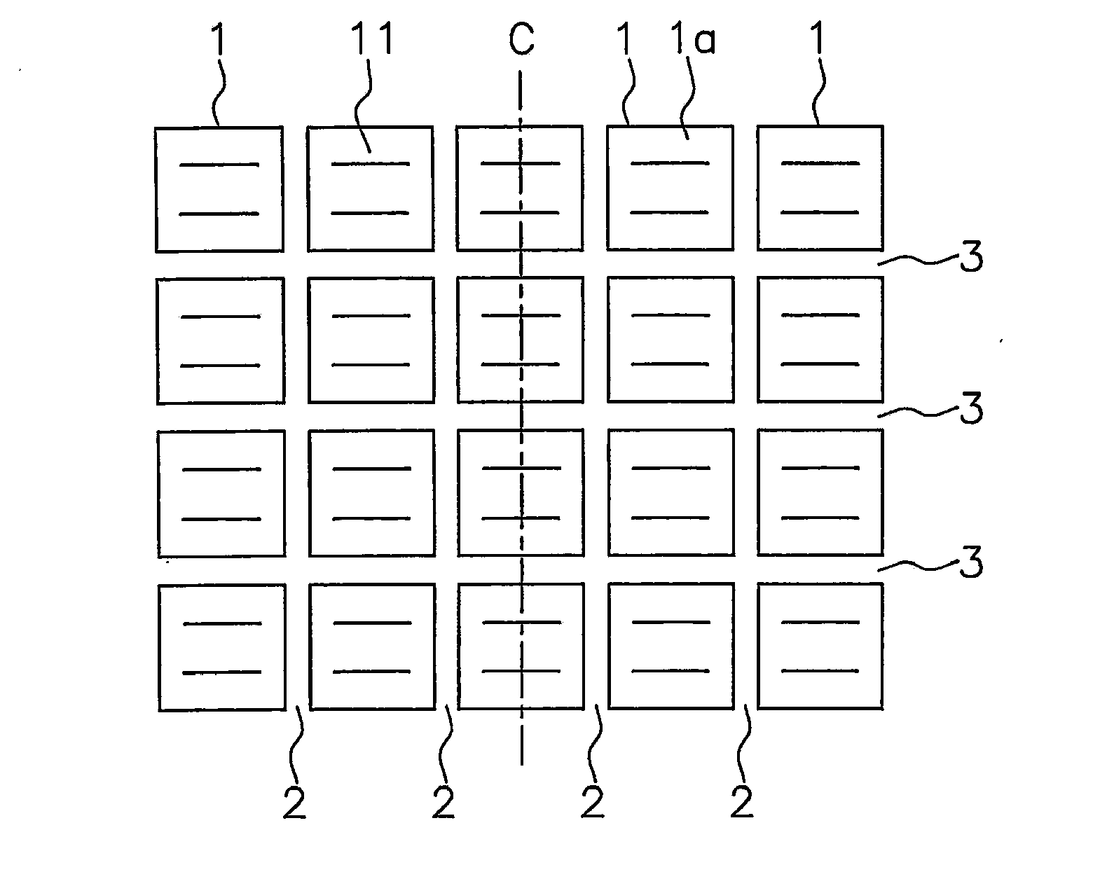
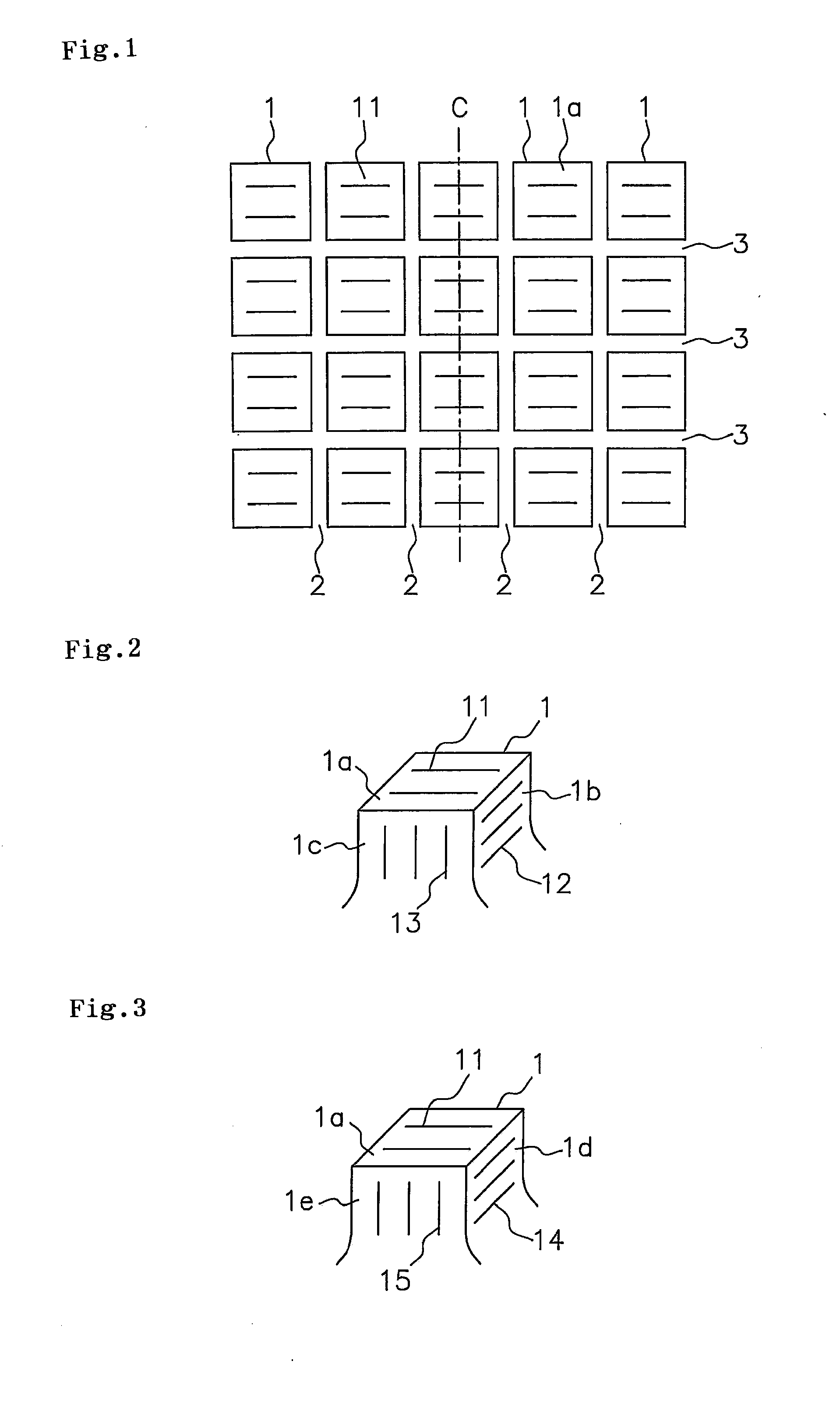
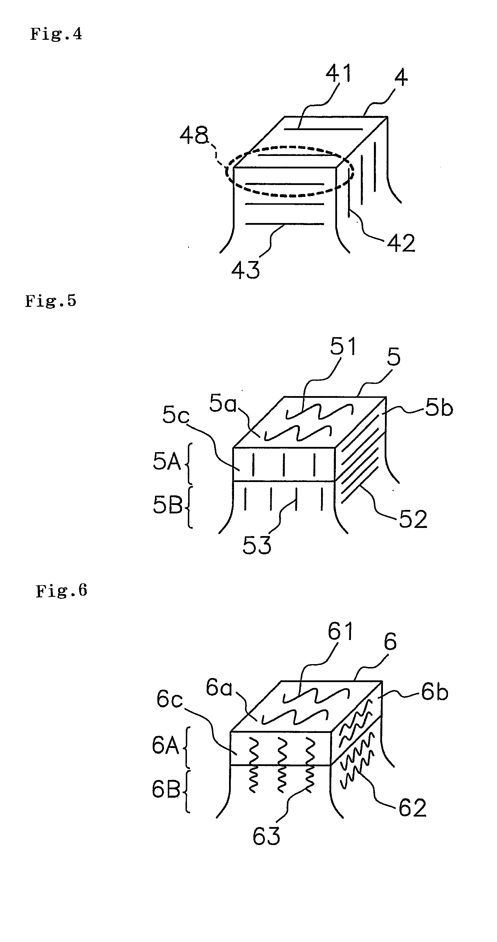
[0053]In the tire having the tread pattern shown in FIG. 1, the tire having the block structure shown in FIGS. 2 and 3 is set to an example 1, the tire having the block structure shown in FIG. 5 is set to an example 2, the tire in which two wall surface sipes 52 are formed in each of the upper layer portion 5A and the lower layer portion 5B in FIG. 5, and three wall surface sipes 53 are formed therein is set to an example 3, the tire having the block structure shown in FIG. 6 is set to an example 4, and the tire in which the wave number of the wall surface sipes 62 and 63 in the lower layer portion 6B in FIG. 6 is set to the same as the upper layer portion 6A is set to an example 5.

[0054]In the comparative examples 1 to 3, and the example 1, the rubber hardness of the block is set to 45 degrees. In the examples 2 to 5, the rubber hardness of the upper layer portion of the block is set to 45 degrees, and the rubber hardness of the lower layer portion is set to 55 degrees. Further, th...


PUM


Abstract

A pneumatic tire has an upper surface sipe formed on an upper surface of the block, a first wall surface sipe formed in a first wall surface of the block and extending in a direction intersecting the upper surface sipe, and a second wall surface sipe formed in a second wall surface which is adjacent to the first wall surface, and extending in a direction intersecting the upper surface sipe and the first wall surface sipe.

Description

BACKGROUND OF THE INVENTION[0001]1. Field of the Invention[0002]The present invention relates to a pneumatic tire provided with a block in a tread surface, and is particularly useful as a studless tire.[0003]2. Description of the Related Art[0004]Conventionally, in the studless tire, a cut called as a sipe is formed in a block of a tread surface, and a traveling performance on an iced road surface having a low coefficient of friction is enhanced based on an edge effect and a drainage effect generated by the sipe. As the sipe mentioned above, a linear sipe and a waveform sipe are put to practical use, the linear sipe extending linearly along a longitudinal direction, and the waveform sipe extending like a wavy form or a zigzag form.[0005]The inventor of the present invention pays attention to a fact that a motion of the block is great on the iced road surface, and a ground contact pressure within the block tends to be uneven due to the motion, for further enhancing the traveling perf...

Claims


Application Information

Patent Timeline
Patent Type & Authority Applications(United States)
IPC IPC(8): B60C11/117
CPCB60C11/11B60C11/12Y10S152/902B60C2011/1254Y10S152/03B60C11/13
Inventor NAGAI, KUNIHIKO
Owner TOYO TIRE & RUBBER CO LTD
Why Eureka
Try Eureka