
Image Forming Apparatus, Charge Server and Image Forming System

Inactive Publication Date: 2009-07-16
KYOCERA DOCUMENT SOLUTIONS INC
View PDF8 Cites 72 Cited by
  • Summary
  • Abstract
  • Description
  • Claims
  • Application Information

AI Technical Summary

Benefits of technology

[0017]Accordingly, an objective of this invention is to provide an image forming apparatus and an image forming system in which even if the charge server can not receive a job log from the image forming apparatus temporarily, the image forming apparatus can handle a next process, and the charge server can perform charge management.
[0075]According to the seventeenth aspect, the user of the second user ID can pretend to be a user of the first user ID. Therefore, existent programs can be used effectively to limit usage with referring to usage limit information when the image forming apparatus is connected to a network.

Problems solved by technology

In this case, the image forming apparatus can not handle a next process.
In another circumstance, due to increment of users, user authentication information, usage limit information, total usage information and so on can not be stored in a memory in the image forming apparatus.
In addition, in case that one user can use whichever of the image forming apparatuses, usage limitation can not be done adequately.

Method used


Image

  • Image Forming Apparatus, Charge Server and Image Forming System
  • Image Forming Apparatus, Charge Server and Image Forming System
  • Image Forming Apparatus, Charge Server and Image Forming System

Examples


embodiment 1

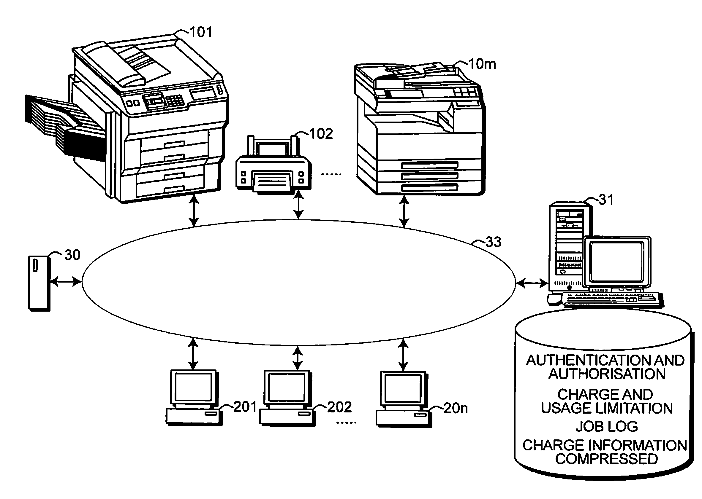
[0099]FIG. 6 shows a schematic block diagram of an image forming system according to Embodiment 1 of this invention.

[0100]M image forming apparatuses 101 to 10m, n clients 201 to 20n, a print server 30, and a management server 31 are connected as nodes to a LAN (Local Area Network) 33. The image forming apparatus 10i (i=1 to m) is a multi function peripheral, a printer, a facsimile machine, or the like.

[0101]The print server 30 has a storage device that stores an OS (Operating System), a server program, and an application program to embody its functions. The OS includes printer drivers of the image forming apparatuses 101 to 10m, a print spooler, and a network interface driver. The network driver communicates with the clients 201 to 20n and the image forming apparatuses 101 to 10m, for example, according to LPR protocol.

[0102]FIG. 6 shows a case that the system has one print server 30, but it is also possible to set up print servers for respective groups of the image forming apparat...

embodiment 2

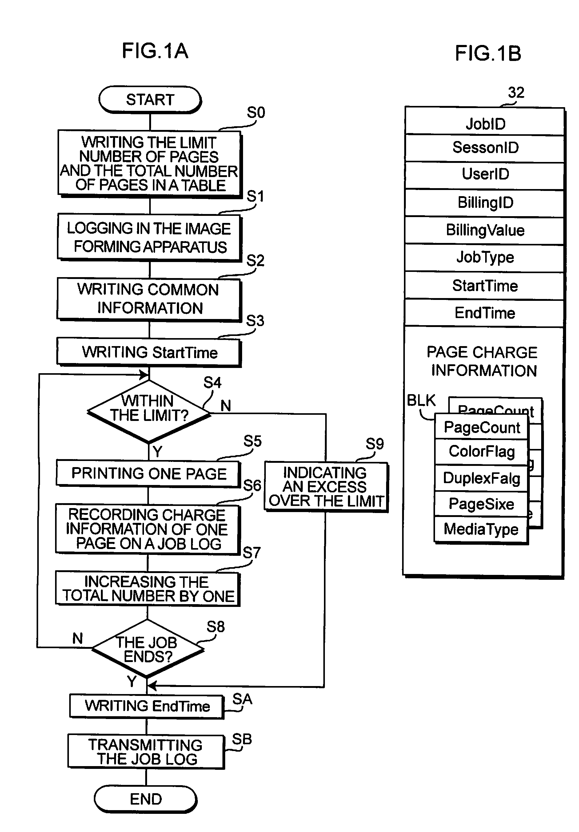
[0179]Information on charge to printing includes information on whether color printing or not, information on whether duplex printing or not, a page size, and sheet type. Some jobs contain both color printing and monochrome printing, or both duplex printing and simplex printing, or different sheet sizes and types. In these cases, when every page is finished printing, it is determined whether or not charge information of the page is the same as any of the existent information blocks BLK, and if charge information of the page is different from all of the existent information blocks BLK, a new information block BLK is generated of the page. Therefore, processes to be executed when every page is finished printing are complicated.

[0180]In FIG. 6, the image forming apparatuses 101 to 10m sometimes stay in a waiting state due to job concentration. On the other hand, processes in the management server 31 are relatively light, and the management server 31 can perform the charge management in...

embodiment 3

[0205]When the management server 31 can not receive a job log due to a power cut or a program crash in the management server 31 or the image forming apparatus, a problem on a wired / wireless connection, or the like, i.e. when the image forming apparatus does not receive the acknowledgement in Step C30 of FIG. 5, in general, the image forming apparatus repeatedly transmits the job log to the management server 31 until it receives an acknowledgement. Therefore, the image forming apparatus does not start executing a next job until it receives an acknowledgement.

[0206]However, in Embodiment 3, if the image forming apparatus 101 does not receive an acknowledgement within a predetermined time after transmitting a job log to the management server 31, it stores the job log in the PROM 13 temporarily, and transmits the temporarily stored job log (i.e. the unprocessed job log) with a next job log to the management server 31 when a next job is finished.

[0207]FIG. 14 shows a flowchart of detaile...


PUM


Abstract

An image forming apparatus has a communication interface, a processor, and a storage unit. The storage unit stores a job log and a job log transmission program. The job log transmission program causes the processor to transmit a job log of a finished job via the communication interface to a charge server connected to a network. The job log transmission program causes the processor to execute the steps of:(a) via the communication interface, determining whether or not the charge server can receive the job log currently, and(b) if it is determined that the charge server can not receive the job log currently, keeping the job log to be transmitted in the storage unit and transmitting the job log kept in the storage unit to the charge server when a job log of a next job is transmitted to the charge server.

Description

CROSS-REFERENCE TO RELATED APPLICATIONS[0001]This application relates to and claims priority rights from a Japanese Patent Applications:[0002]No. 2008-003936, filed on Jan. 11, 2008,[0003]No. 2008-003937, filed on Jan. 11, 2008,[0004]No. 2008-003938, filed on Jan. 11, 2008, and[0005]No. 2008-003939, filed on Jan. 11, 2008,the entire disclosures of which are hereby incorporated by reference herein.BACKGROUND OF THE INVENTION[0006]1. Field of the Invention[0007]This invention relates to image forming apparatus, charge server, and image forming system.[0008]2. Description of the Related Art[0009]In an environment, a user can choose one from image forming apparatuses, and uses it for copying, printing or transmitting facsimile data. In the environment, to perform charge management for each of users or each of sections, a charge server is connected to a network with the image forming apparatuses, and every time when a job ends in one of the image forming apparatuses, a job log is transmi...

Claims


Application Information

Patent Timeline
IPC IPC(8): G06F3/12
CPCG03G15/5075G06F3/1294H04N1/32502H04N1/00915G06Q30/04G06F3/1222G06F3/1238G06F3/1273G06F3/1288G06F21/608
Inventor TAKAISHI, HIROYUKIYASUI, TORU
Owner KYOCERA DOCUMENT SOLUTIONS INC
Learn More