
Socket for mounting electronic component

Inactive Publication Date: 2009-07-16
SONY CORP +1
View PDF10 Cites 5 Cited by
  • Summary
  • Abstract
  • Description
  • Claims
  • Application Information

AI Technical Summary

Benefits of technology

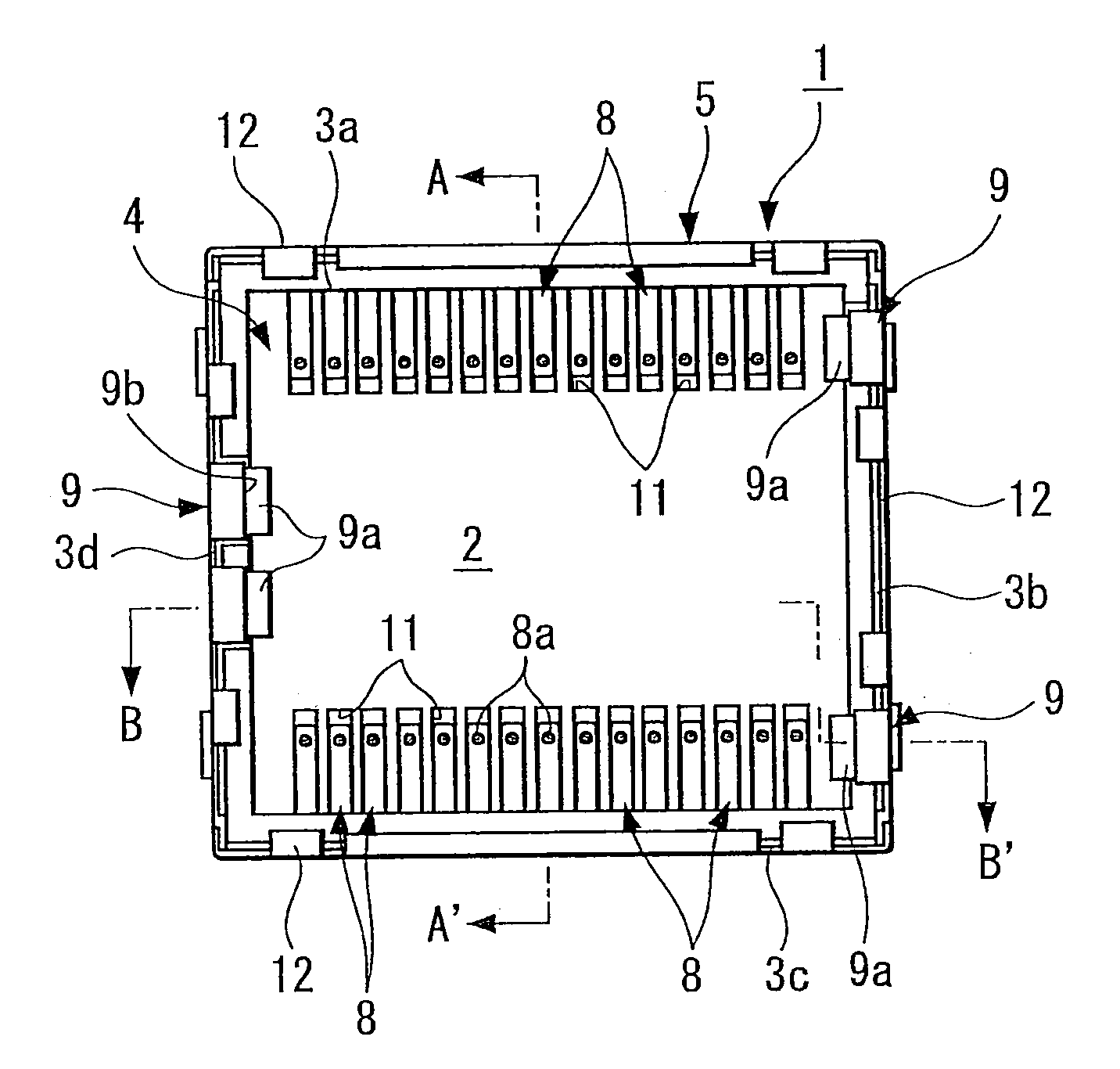
[0008]The first invention is applied to a socket for mounting an electronic component with a configuration including a socket housing having an electronic component accommodating part that is surrounded by a peripheral wall raised from the four side parts of a quadrangle-shape bottom plate, a plurality of contacts protruding from the bottom plate of the socket housing and having elastic contact pieces elastically contacting a plurality of terminal parts in a bottom part of an electronic component in the electronic component accommodating part to be electrically connected, and socket-side engaging parts provided at a plurality of places of the peripheral wall of the socket housing and configured to engage with electronic-component-side engaging parts of an electronic component to be inserted into the electronic component accommodating part to prevent coming-off of the electronic component. Further, the invention is applied to a socket for mounting an electronic component having a configuration that the socket-side engaging parts are engaged with the electric component engaging parts and thereby the electronic component is prevented from coming off the electronic component accommodating part.
[0012]According to the second invention, the socket-side engaging parts are arranged substantially in a triangle arrangement, and it is possible to lock the electronic component in a stable posture.
[0014]According to the third invention, the locking state of the electronic component becomes more stable.
[0016]According to the fourth invention, if the electronic component is inserted in the orientation other than a specified one, the electronic component is hard to be inserted because of the elastic fixing pieces, and when the electronic component is inserted in the correct orientation, insertion is easy and yet, after having been inserted, the elastic fixing pieces are locked in the engaging recessed parts of the peripheral wall of the electronic component and thereby the electronic component is put in a stable locked state.

Problems solved by technology

However, with such symmetrical arrangement of these socket-side engaging parts for the socket for mounting an electronic component, when inserting an electronic component into the electronic component accommodating part of the socket housing, even when the electronic component is inserted 180 degrees reversed, it results in that the electronic component is locked in respective socket-side engaging parts, so that there has been a problem that the connection always in the correct orientation cannot be guaranteed.

Method used


Image

  • Socket for mounting electronic component
  • Socket for mounting electronic component
  • Socket for mounting electronic component

Examples


Embodiment Construction

[0027]Next, a concrete example of a socket for mounting an electronic component according to an embodiment of the present invention is described in detail while referring to drawings.

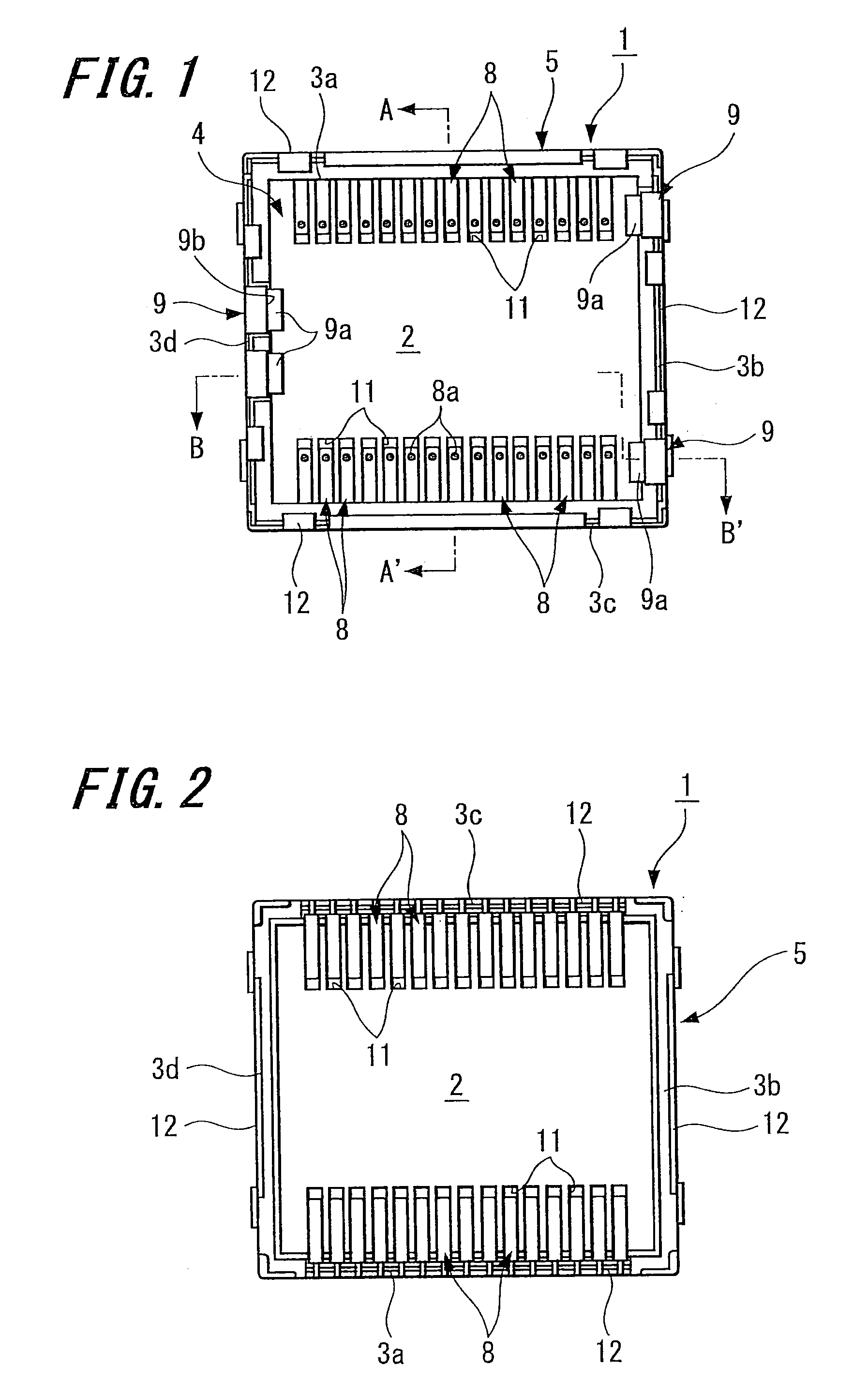
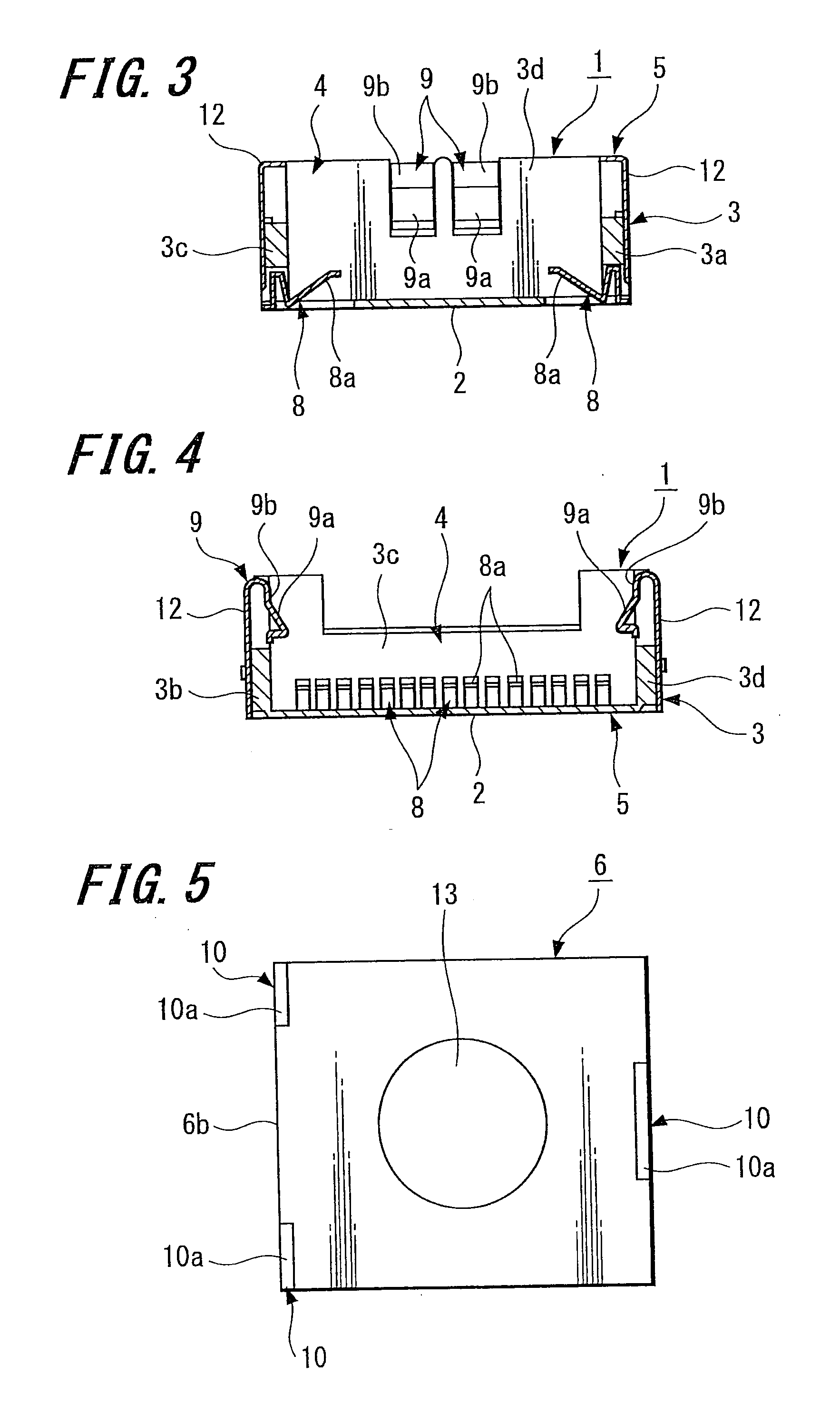
[0028]FIG. 1 through FIG. 4 illustrates an example of a socket for mounting an electronic component according to an embodiment of the present invention. FIG. 1 is a front view of the socket for mounting an electronic component of the example according the present embodiment. FIG. 2 is a back view of the socket. FIG. 3 is a cross section along an A-A′ line of FIG. 1. FIG. 4 is a cross section along a B-B′ line of FIG. 1.

[0029]FIG. 5 through FIG. 8 illustrates an example of an electronic component, such as a cameral module, etc., that is inserted into the socket for mounting an electronic component of the example according to the present embodiment. FIG. 5 is a front view of the electronic component, FIG. 6 is a bottom view of FIG. 5, FIG. 7 is a right side view of FIG. 5, and FIG. 8 is a back view of FIG...


PUM


Abstract

A socket for mounting an electronic component that can connect an electronic component always in a correct orientation is provided. Socket-side engaging parts (9) are provided at a plurality of places of a peripheral wall (3) of a socket housing (5) having an electronic component accommodating part (4) that is surrounded by the peripheral wall (3) raised from the four side parts of a quadrangle-shape bottom plate (2). The socket-side engaging parts (9) include elastic fixing pieces whose fixing protrusions (9a) at the tip ends are locked in the bottom parts of respective locking recessed parts of the peripheral wall of the electronic component (6). An electronic component is held in the electronic component accommodating part (4) by these socket-side engaging parts (9). In one side part (3d) of opposing two side parts (3b), (3d) of the peripheral wall (3) of the four side parts (3a), (3b), (3c), (3d) of the socket housing (5), plural socket-side engaging parts (9) are arranged closer to the both end sides thereof with an interval in between, and in the remaining other side part (3b), one or plural socket-side engaging parts are arranged closer to the center side thereof adjacent to each other.

Description

TECHNICAL FIELD[0001]The present invention relates to a socket for mounting an electronic component, such as a sensor module such as a camera module and the like used in a mobile phone, etc., a semiconductor element, etc., to a printed wiring board in a state of being electrically connected to the printed wiring board.BACKGROUND ART[0002]Conventionally, an electronic apparatus such as a mobile phone, etc. is provided with a printed wiring board inside thereof, and an electronic component such as a sensor module, other semiconductor elements, etc. is mounted to the printed wiring board. In this case, because the electronic component that is easily affected by heat cannot be directly mounted by means of soldering, such component is connected to the printed wiring board using a socket for mounting an electronic component.[0003]A socket for mounting an electronic component includes a socket housing having an electronic component accommodating part that is surrounded by a peripheral wall...

Claims


Application Information

Patent Timeline
IPC IPC(8): H01R12/00
CPCH01R12/7076H01R13/6271H05K7/1069H01R13/65802H01R13/64H01R13/6583H01R33/74H01R33/76
Inventor KUSAKI, KENJIASAI, KIYOSHI
Owner SONY CORP
Learn More