Caching Method and Apparatus for a Vertex Shader and Geometry Shader

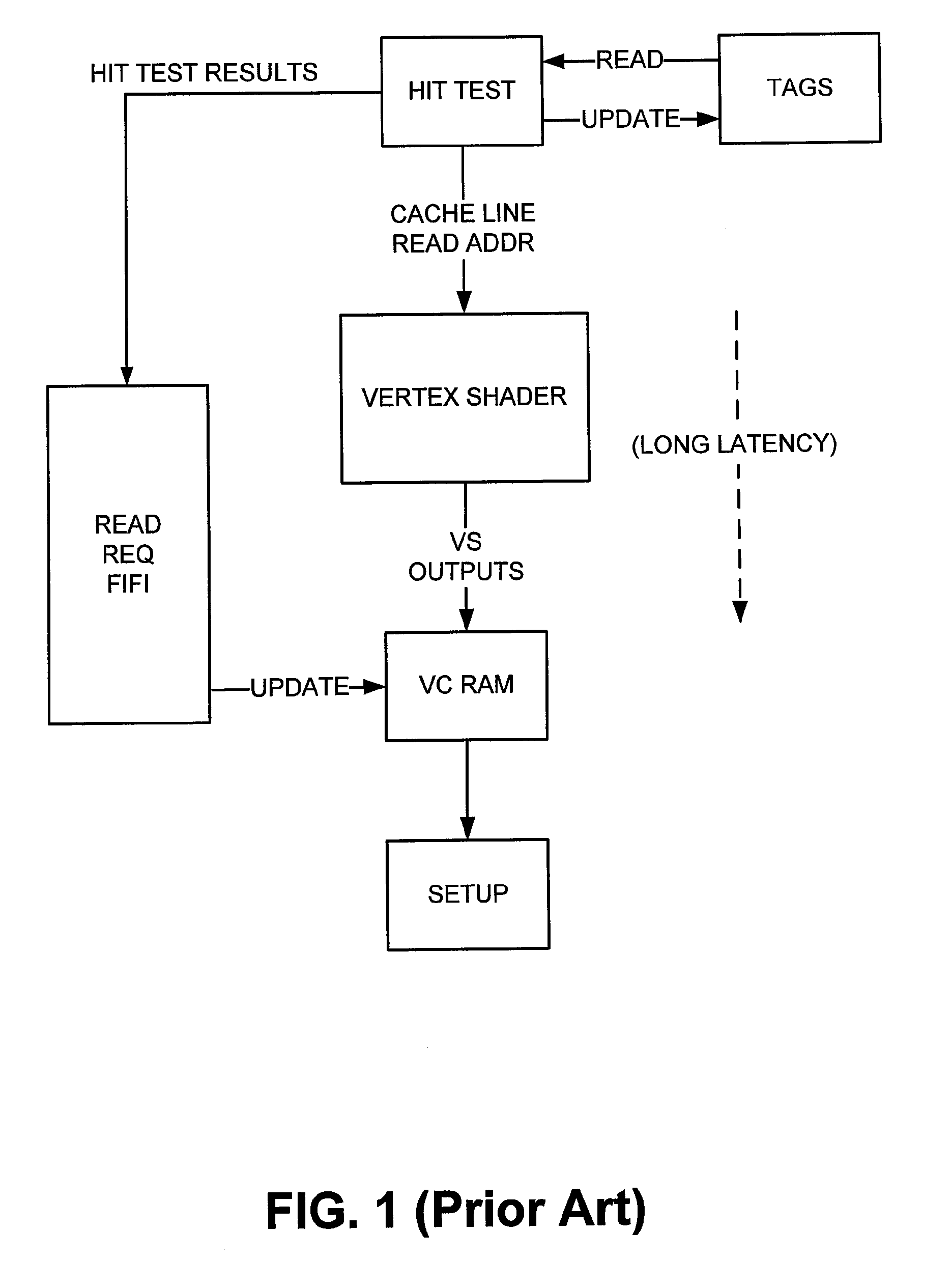
a shader and geometry technology, applied in computing, memory adressing/allocation/relocation, instruments, etc., can solve the problems of significant latency between cache hit test and data read, cache frequently stalls, and cache hit test and subsequent line replacement are stalled

Active Publication Date: 2009-07-16
VIA TECH INC
View PDF4 Cites 49 Cited by
  • Summary
  • Abstract
  • Description
  • Claims
  • Application Information

AI Technical Summary

Benefits of technology

[0012]Briefly described, one embodiment, among others, is directed to a system for sharing caches between two or more clients. The system comprises a physical cache memory having a memory portion accessed through a cache index. The system further comprises at least two virtual cache spaces mapping to the memory portion and at least one virtual cache controller configured to perform a hit-miss test on the active window of the virtual cache space in response to a request from one of the clients for accessing the physical cache memory. In accordance with some embodiments, each of the virtual cache spaces has an active window which has a different size than the memory portion. Furthermore, data is accessed from the corresponding location of the memory portion when the hit-miss test of the cache index returns a hit.

Problems solved by technology

Reference is made to FIG. 1, which shows a prior art arrangement of a vertex cache Read Request FIFI, a problem occurs when the hardware performs a hit test long before the data is updated in the cache and read by the next pipeline stage unit (e.g., the setup engine).
However, when the reference count in all the lines is not equal to zero, the cache hit test and the subsequent line replacement is stalled.
Since the VS execution may take a long time to complete, there is significant latency between the cache hit test and data read.
When the cache size is small, the cache frequently stalls due to the long latency, blocking hit test.
However, one perceived shortcoming is that the cost is high because more cache tags and comparators are needed.
Furthermore, above a certain size, adding more cache lines with tags does not increase the cache hit rate significantly and cost remains an issue.
Second, when the actual data placement is tied to the tag at the front in a set-associative cache, the cache RAM is not fully utilized when the cache conflict is high (i.e., the requests are not evenly distributed into all sets and there are a lot of requests hit in one set).
Consequently, the very different access patterns make the design of a vertex cache difficult.
Therefore, a heretofore unaddressed need exists in the industry to address the aforementioned deficiencies and inadequacies.

Method used


Image

  • Caching Method and Apparatus for a Vertex Shader and Geometry Shader
  • Caching Method and Apparatus for a Vertex Shader and Geometry Shader
  • Caching Method and Apparatus for a Vertex Shader and Geometry Shader

Examples


Embodiment Construction

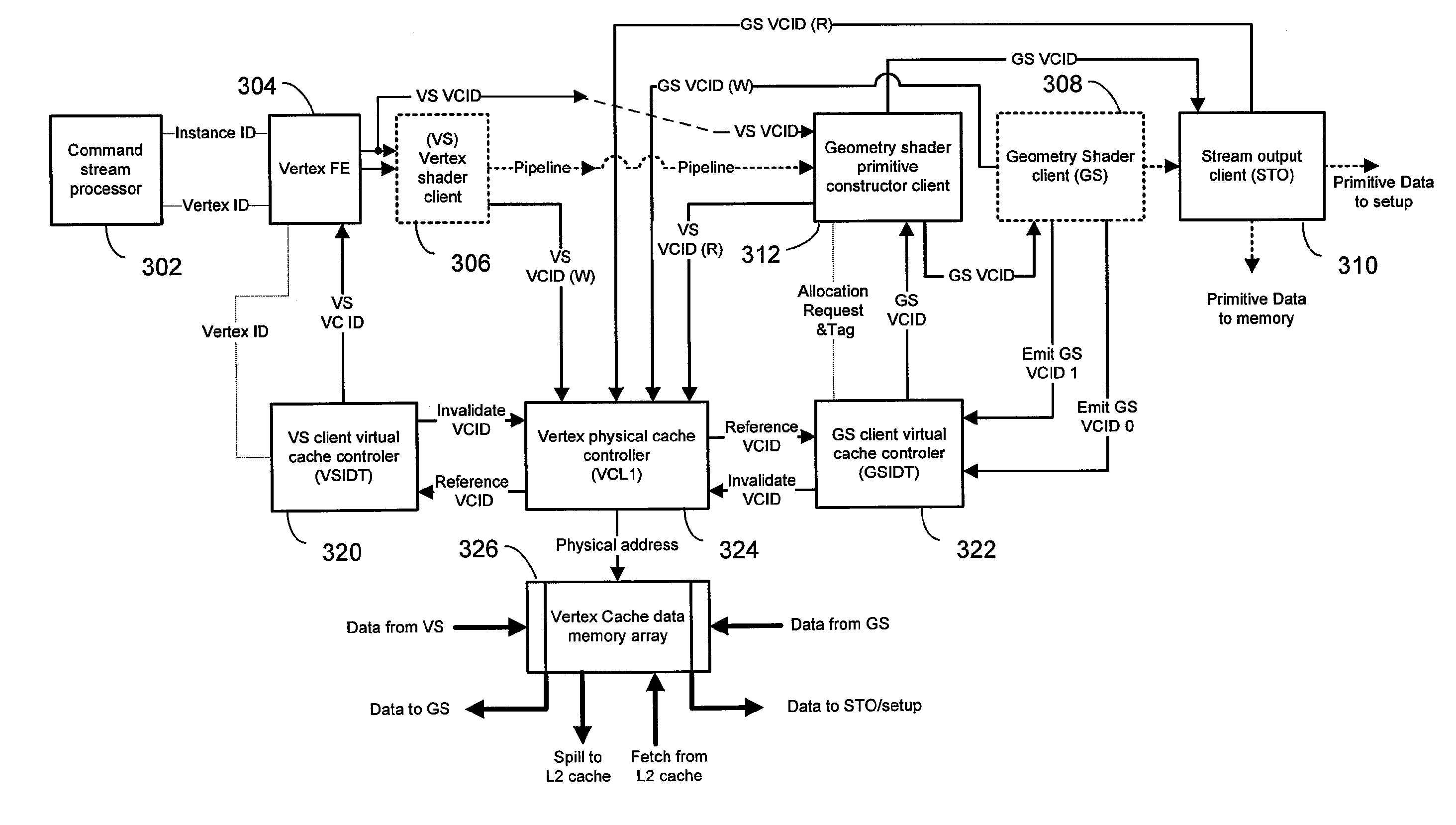
[0027]Various embodiments of the present invention address the perceived shortcomings of the prior art approaches described above and provide a cache design that minimizes the stalling that may occur due to the processing of hits and long latencies experienced by the VS unit. Embodiments described herein provide for flexible buffer sizes within the cache in order to meet the needs of the GS and the VS units while allowing both the GS and VS units to share the same cache.

[0028]Exemplary embodiments of the present invention described herein employ a pair of virtual caches that are separate from the physical cache controller. A set of virtual tags is decoupled from the physical tags of the physical cache. The actual number of physical cache entries may be smaller or larger than the number of virtual tag entries (e.g., for one embodiment, it may be larger for higher hit rates in order to improve average latency). The result of a hit test on the virtual tag is an address in the physical ...


PUM


Abstract

Systems and methods for sharing a physical cache among one or more clients in a stream data processing pipeline are described. One embodiment, among others, is directed to a system for sharing caches between two or more clients. The system comprises a physical cache memory having a memory portion accessed through a cache index. The system further comprises at least two virtual cache spaces mapping to the memory portion and at least one virtual cache controller configured to perform a hit-miss test on the active window of the virtual cache space in response to a request from one of the clients for accessing the physical cache memory. In accordance with some embodiments, each of the virtual cache spaces has an active window which has a different size than the memory portion. Furthermore, data is accessed from the corresponding location of the memory portion when the hit-miss test of the cache index returns a hit.

Description

FIELD OF THE INVENTION[0001]The present application relates generally to implementation of a programmable graphics pipeline in a GPU and more particularly to the use of a shared common vertex data cache for vertex shader and geometry shader programs executing in a pool of parallel processing units.DESCRIPTION OF THE RELATED ART[0002]The present art implements graphics pipelines using only a vertex shader (VS) and pixel shader (PS) programs assigned to separate processing units located in different stages of a GPU pipeline. As generally known, a vertex shader generally operates efficiently with a dedicated vertex cache because data can be provided as needed. No special sorting of the data for processing is required. Conventional vertex caches, however, have a number of drawbacks. Reference is made to FIG. 1, which shows a prior art arrangement of a vertex cache Read Request FIFI, a problem occurs when the hardware performs a hit test long before the data is updated in the cache and r...

Claims


Application Information

Patent Timeline
Patent Type & Authority Applications(United States)
IPC IPC(8): G06F12/08
CPCG06F12/084G06F12/0875G06F12/0864
Inventor JIAO, JEFFPALTASHEV, TIMOUR
Owner VIA TECH INC
Why Eureka
Try Eureka