Liquid cooling system for internal combustion engine

Inactive Publication Date: 2009-07-23
FORD GLOBAL TECH LLC
View PDF14 Cites 7 Cited by
  • Summary
  • Abstract
  • Description
  • Claims
  • Application Information

AI Technical Summary

Benefits of technology

[0011]According to another aspect of the present invention, the thermostatic valve has at least a first position in which the primary valve element is closed and the bypass flow control is open to a maximum extent and a second position in which the primary valve element is open and the bypass flow control is open to a minimum extent.
[0012]According to another aspect of the present i

Problems solved by technology

This has presented a problem with known

Method used


Image

  • Liquid cooling system for internal combustion engine
  • Liquid cooling system for internal combustion engine
  • Liquid cooling system for internal combustion engine

Examples


Embodiment Construction

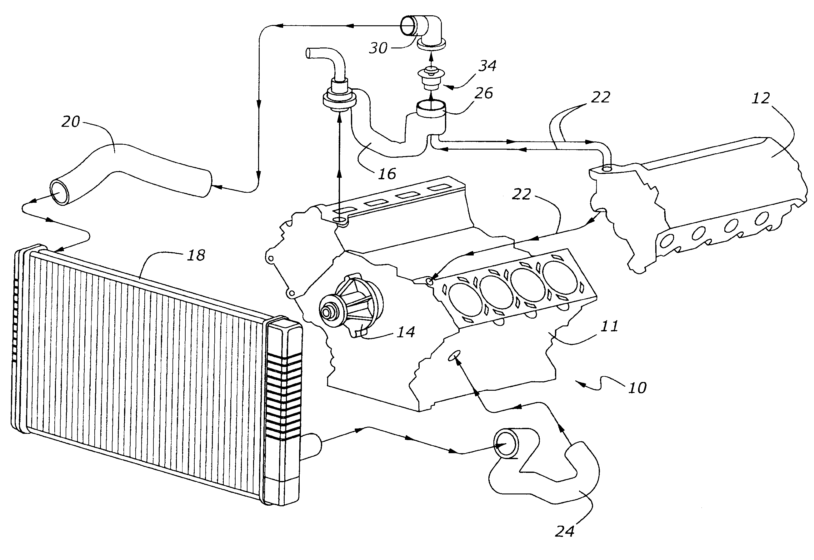
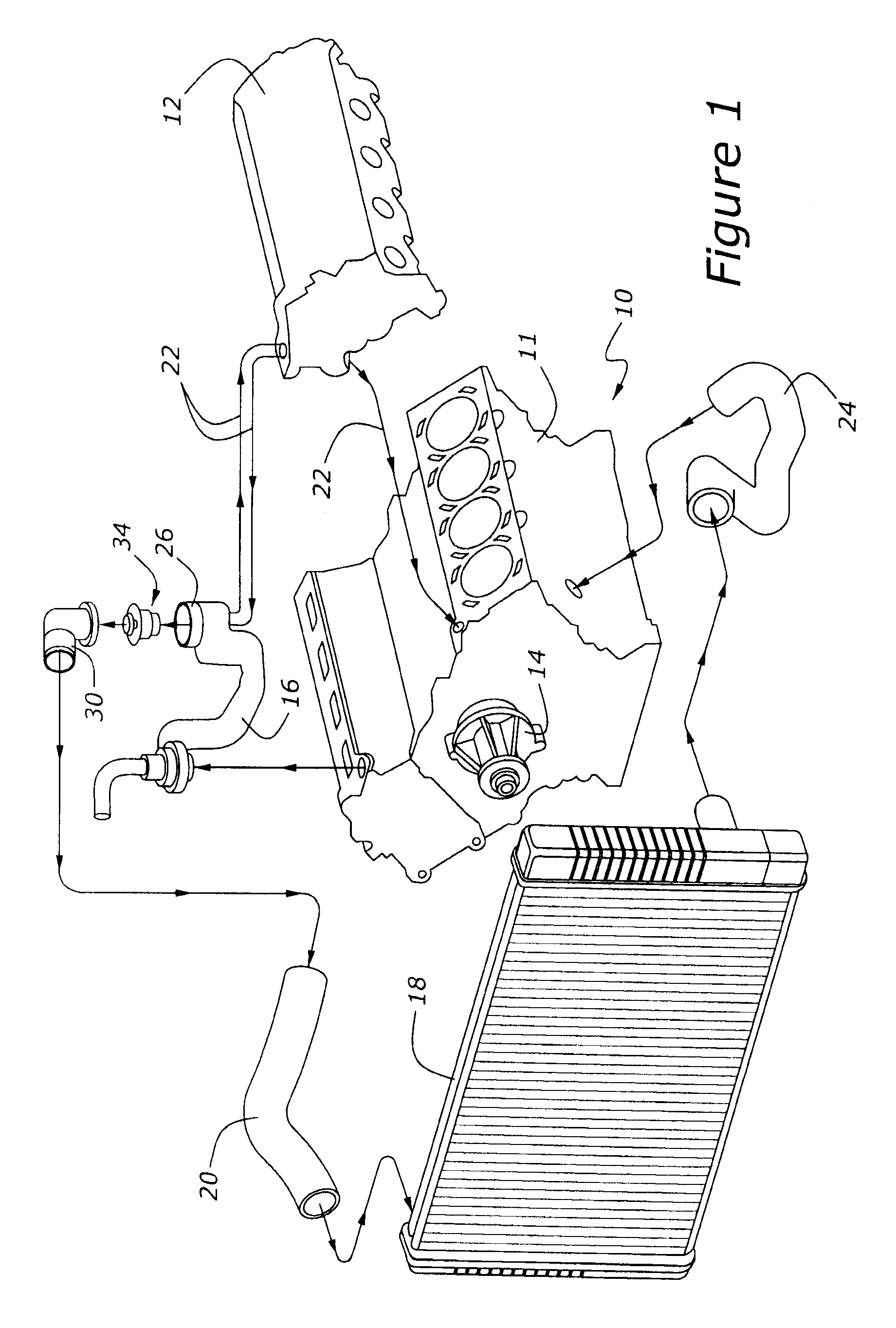
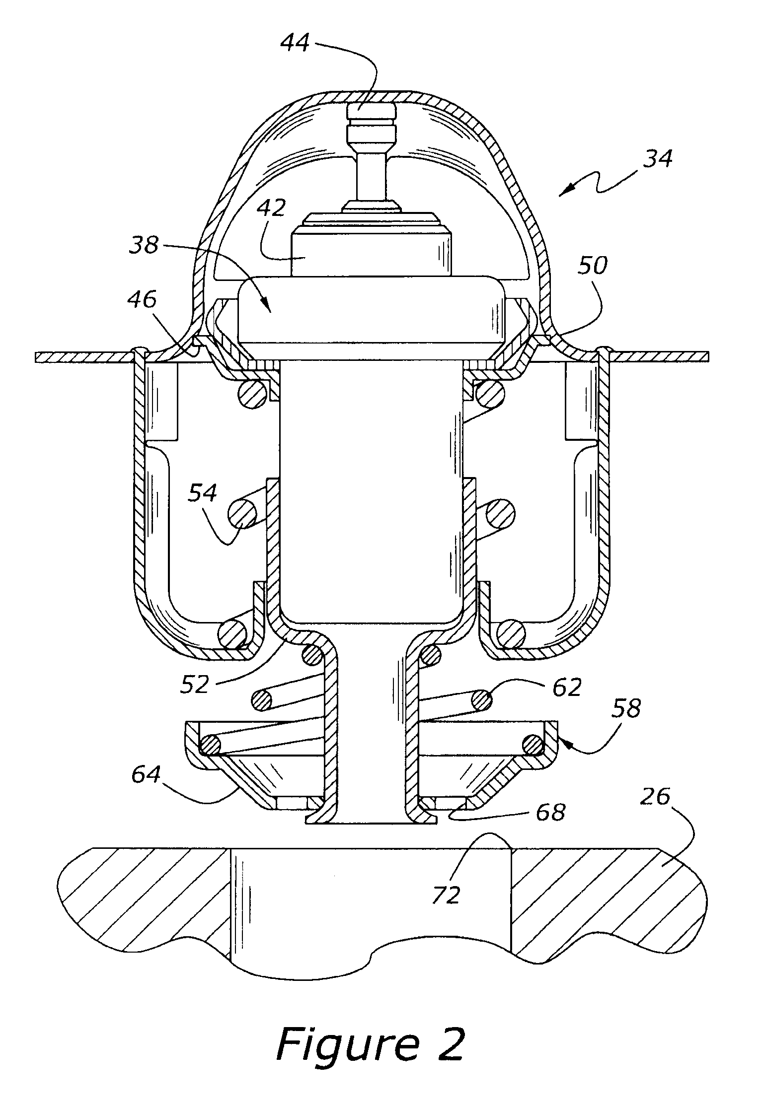
[0019]As shown in FIG. 1, engine 10 has a cylinder block, 11, upon which a pair of cylinder heads, 12, are mounted, with only one of cylinder heads 12 being shown. Engine 10 also includes a coolant pump, 14, a coolant crossover, 16, an air-to-liquid heat exchanger (“radiator”) 18, and a series of hoses. Coolant circulates generally from water pump 14 through cylinder block 11 and up through cylinder heads 12. After moving through cylinder heads 12, coolant flows into thermostat housing 26 which, as its name implies, provides a mounting place for thermostatic valve 34, including a bypass valve seat, 72 (FIGS. 2 and 3). When thermostatic valve 34 is in the open position shown in FIG. 3, coolant flows up through thermostatic valve 34 and then through coolant outlet 30 and upper radiator hose 20, and then into radiator 18. The cooled fluid then moves through lower radiator hose 24 and then through water pump 14. Leaving water pump 14, the fluid flows back through cylinder block 11, as d...


PUM


Abstract

A liquid cooling system for an internal combustion engine includes a coolant pump, an air-to-liquid heat exchanger, and a bypass loop for allowing coolant to circulate from the coolant pump to the engine without passing through the heat exchanger. A thermostatic valve mounted within a thermostat housing and including a temperature-responsive primary valve element and bypass flow control will control the flow of coolant with a spring-loaded valve disc having a conical, annular sealing surface configured for linear contact with the valve seat.

Description

CROSS REFERENCE TO RELATED APPLICATIONS[0001]None.BACKGROUND OF THE INVENTION[0002]1. Field of the Invention[0003]This disclosure relates to a liquid cooling system for a reciprocating internal combustion engine.[0004]2. Related Art[0005]Automotive internal combustion engines operate in a variety of temperature extremes. The first duty of a cooling system is to maintain the engine's operating temperature within a fairly narrow range. As exhaust emission control requirements tighten, this function has increased in importance.[0006]In addition to controlling the ultimate temperature at which an engine operates following warm up, the cooling system desirably provides rapid warm up of the engine so as to provide heat to the passenger cabin of a vehicle as quickly as possible. To this end, coolant is circulated through a bypass, which allows the coolant to move through the engine without passing through the air-to-liquid heat exchanger, commonly termed a radiator. Once the engine attains...

Claims


Application Information

Patent Timeline
IPC IPC(8): F01P7/16
CPCF01P2070/00F01P7/16
Inventor O'FLYNN, KEVIN P.SLIKE, JODY M.
Owner FORD GLOBAL TECH LLC
Why Eureka
Try Eureka