Packaging unit for articles with opening feature

a packaging unit and opening feature technology, applied in the field of semirigid packaging units, can solve the problems of inconvenient user and difficulty in opening, and achieve the effect of convenient user grasping and a large surface area

Inactive Publication Date: 2009-07-23
THE GILLETTE CO
View PDF13 Cites 16 Cited by
  • Summary
  • Abstract
  • Description
  • Claims
  • Application Information

AI Technical Summary

Benefits of technology

[0023]An advantage of the invention has been determined to exist in that users intuitively understand to grasp opening tab 24 to open the packaging unit 10, thus eliminating the need for extensive opening instructions to be printed on the package, which permits more of the finite surface area of the package to be available for viewing the article and communicating substantive information about vended article itself.
[0024]Perforations 16 can be any convenient weakening and / or stress-concentrating features such as made by mechanical die cutting or slitting. The perforations 16 can be formed to extend through back wall 12 as might conveniently be done with die cutting or slitting. Depending on the material, as understood in the art 100 percent cuts (slits extending through 100% of the thickness) could be sufficient. Perforations 16 are formed to completely extend through back wall 12, such as by cutting fully through the material's thickness, as is presently preferred. It is presently preferred to form the perforations as 10 mm long running slits with 1 mm of un-slit portion (“land”) between the slits when using PVC, PET G, PET, PETGAG, or PP sheets of about 0.4 mm thickness, it being understood that the choice of dimensions would be made by one of skill in the art in light of the thickness and stiffness of the wall material. The perforations 16 can be formed subsequent the formation of the plastic material back wall 12. It is preferred that perforations 16 be done in the blank for back wall 12 before the front and back walls 11, 12 are heat-welded together, since then the wall forming step can be done in one operation; otherwise, if the perforations 16 were formed after the walls are heat-welded, that would require an additional processing step.
[0025]The article within packaging unit 10 may be an article of personal use, such as a razor, a razor blade unit, a shaving unit, a shaving head, a toothbrush, a battery, an energy or other fuel cell for an electric or gas powered appliance, or the like.
[0026]Referring now to FIG. 6, there is shown another packaging unit 110 of the present invention. Packaging unit 110 is identical to packaging unit 10 of FIGS. 1-5, with one distinction. The one distinction is that line of weakness 115 allows opening flap 120 to be completely removed or separated from the remainder of back wall 112.
[0027]The line of weakness 115 defines an opening flap 120. A raised opening tab 124 is positioned on the opening flap 120 along the line of weakness 115. The raised opening tab 124 extends away from the opening flap 120. By extending away from the opening flap 120, the raised tab 124 provides a convenient location for a user to grasp when opening the packaging unit 110. When the perforations 116 of the line of weakness 115 are ruptured, which can be done upon application of a moderate manual force to the opening tab 124, the opening flap 120 can be completely separated from the remainder of the back wall 112 allowing for easy access to the article-receiving region 113.
[0028]The dimensions and values disclosed herein are not to be understood as being strictly limited to the exact numerical values recited. Instead, unless otherwise specified, each such dimension is intended to mean both the recited value and a functionally equivalent range surrounding that value. For example, a dimension disclosed as “40 mm” is intended to mean “about 40 mm.”

Problems solved by technology

It is recognized that various disadvantages of these known packs include they are frequently difficult to open, usually requiring scissors or considerable force, or do not allow easy access to the article within, which is inconvenient for the user.

Method used


Image

  • Packaging unit for articles with opening feature
  • Packaging unit for articles with opening feature
  • Packaging unit for articles with opening feature

Examples


Embodiment Construction

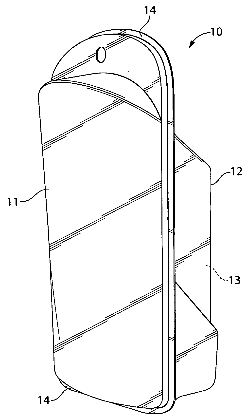
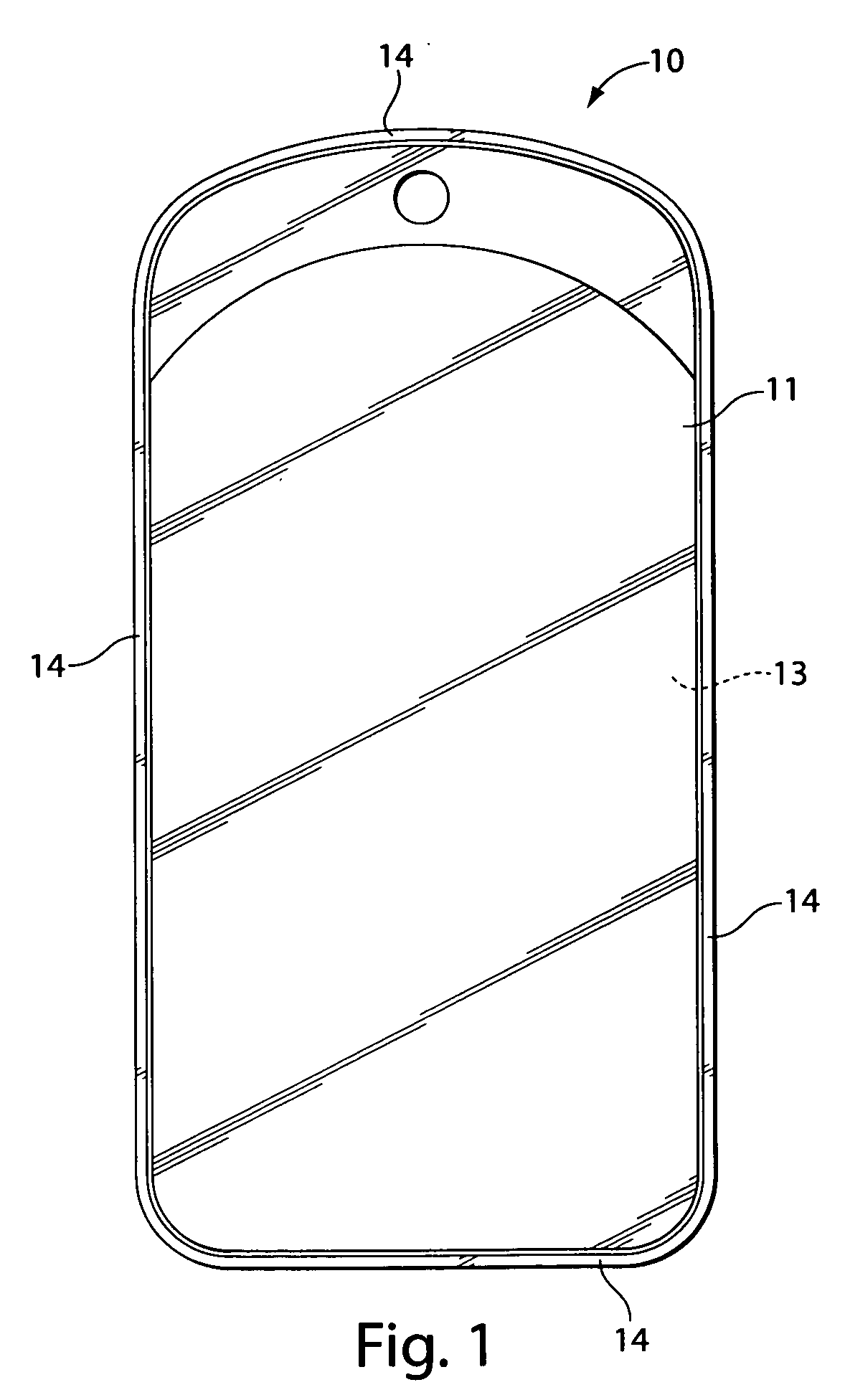
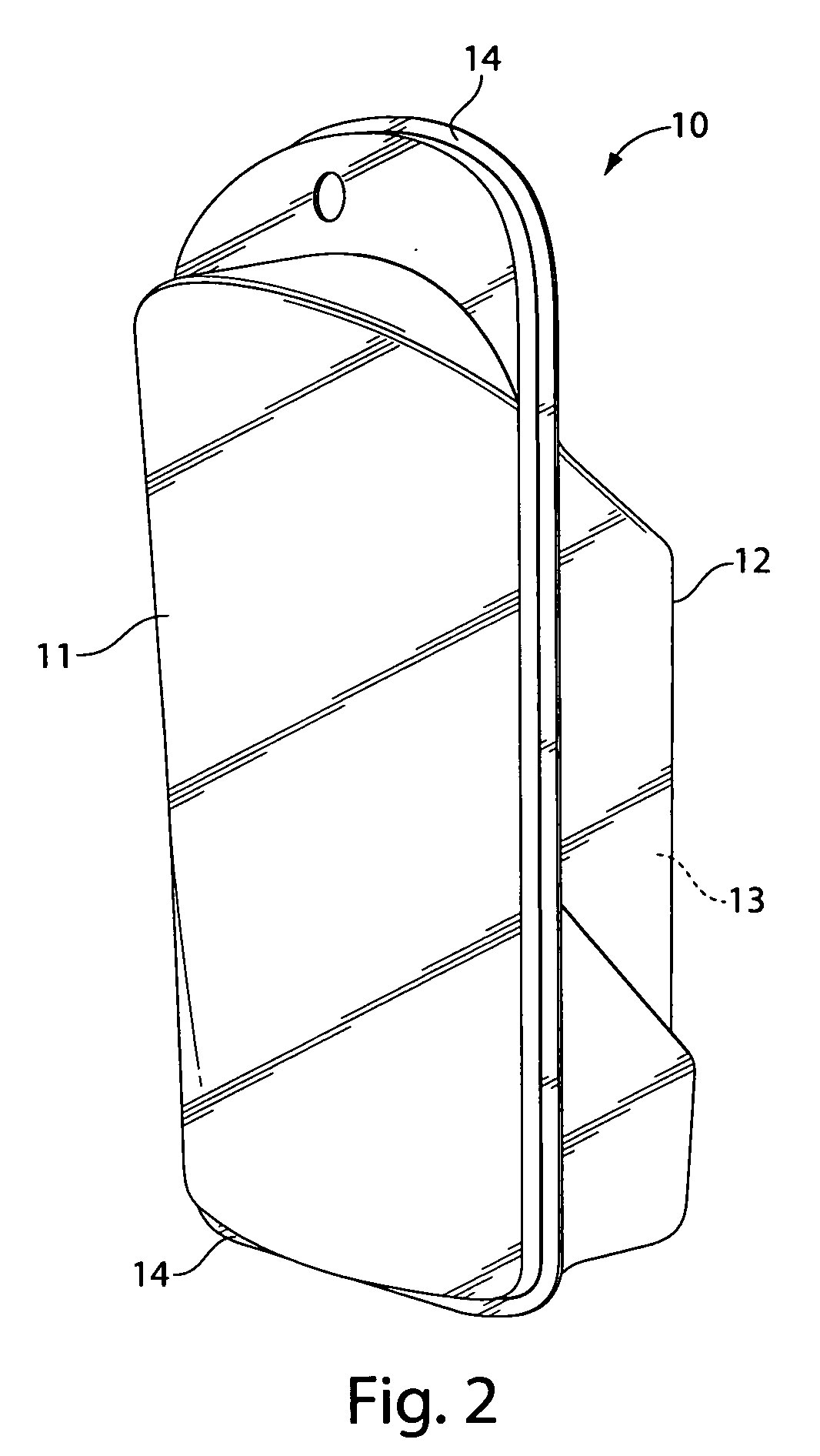
[0018]Referring to FIGS. 1 through 3, there is shown a packaging unit 10 for articles. The packaging unit 10 is comprised of two spaced-apart walls, front wall 11 and back wall 12 that have been formed to define an article-receiving region 13 between them commonly referred to as a blister, pouch, pocket or cavity. The walls can be referred to as a sheet, foil or panel. The article-receiving pouch shape can be formed into one wall and the other be flat, but it is preferred that both front wall 11 and back wall 12 define parts of the article-receiving pouch. The packaging unit 10 may have a plurality of shapes, including rectangular, circular or oval; preferably, in general, having a rectangular shape. The front wall 11 and back wall 12 are formed of semi-rigid material, which generally retains a shape, e.g. the blister shape, into which it is formed, and is relatively stiff. Preferably the front wall 11 and back wall 12 are formed of plastic material, preferably transparent plastic, ...


PUM

PropertyMeasurementUnit
thicknessaaaaaaaaaa
thicknessaaaaaaaaaa
thicknessaaaaaaaaaa

Abstract

A packaging unit having a front wall and a back wall sealed together at a peripheral joint. The front and back walls are formed of semi-rigid material. The front wall and back wall are spaced apart from one another to define an article-receiving region between them. A line of weakness is formed in the back wall. The line of weakness defines an opening flap to be at least partially separated from the remainder of the back wall. A raised opening tab is positioned on the opening flap along the line of weakness and extends away from the opening flap. The line of weakness is rupturable by a user by applying a manual force to the opening tab to at least partially separate the opening flap from the remainder of the back wall along the line of weakness in order to access the article-receiving region.

Description

FIELD OF THE INVENTION[0001]The present invention is directed to a semi-rigid packaging unit for articles such as razors, articles of personal use and the like.BACKGROUND OF THE INVENTION[0002]Conventional packaging units for articles are made from two walls secured to one another. The walls are relatively stiff with a heat seal weld along the peripheral edges or indeed surrounding the entire periphery. Examples of these packaging units are shown in U.S. Pat. No. 5,429,241 issued to Althaus and U.S. Pat. No. 5,407,066 issued to Grange.[0003]Blister packs are known to have a plastic blister front and a cardboard rear wall, the plastic front being glued to the cardboard, which is opened when the user peels the two halves away from one another or pulls back a perforated flap or panel on the cardboard back wall. Examples of these packs are shown in U.S. Pat. No. 4,095,691 issued to Iten; U.S. Pat. No. 3,972,417 issued to Iten et al.; U.S. Pat. No. 3,970,194 issued to Iten; and U.S. Pat....

Claims


Application Information

Patent Timeline
Patent Type & Authority Applications(United States)
IPC IPC(8): B65D73/00
CPCB65D2575/366B65D75/322
Inventor DOHERTY, ROBERT CHARLES
Owner THE GILLETTE CO
Why Eureka
Try Eureka