Charged Particle Beam Irradiation System

a charge particle and beam technology, applied in the field of charge particle beam irradiation system, can solve the problems of not always following the intensity pattern of the extraction beam, not easy to extract an ion beam at the desired intensity, and not easy to judge, so as to save the time taken to cope with the fluctuation factor and improve the accuracy

Active Publication Date: 2009-07-23
HITACHI LTD
View PDF3 Cites 98 Cited by
  • Summary
  • Abstract
  • Description
  • Claims
  • Application Information

AI Technical Summary

Benefits of technology

[0018]This makes it possible to perform accurate adjustment with fluctuation factors of the intensity of the extracted ion beam correctly kept track of.
[0019]In addition, when an extracted ion beam fluctuates for some unexpected reason, a fluctuation factor thereof can be identified. To be more specific, it is possible to judge whether the fluctuation factor exists in the synchrotron or in the other elements including the beam transport line, the irradiation nozzles, and other devices. Therefore, saving of time taken to cope with the fluctuation factor and an improvement in accuracy can be expected.
[0020]Moreover, in the construction stage of a charged particle beam irradiation system, the intensity of the ion beam extracted from the synchrotron can be adjusted without waiting until the construction of the charged particle beam irradiation system is completed. This enables early startup of the charged particle beam irradiation system.

Problems solved by technology

Therefore, it is not easy to extract an ion beam at the desired intensity.
However, the intensity of the extraction beam does not always follow the intensity pattern that has been estimated.
Moreover, even after the construction of the charged particle beam irradiation system is completed, if an abnormal state of the intensity of an extracted beam is detected, it is not possible to easily judge whether the abnormal state is caused by the extracted beam of the synchrotron or by a malfunction of an element disposed after the synchrotron, which requires a long period of time to investigate the cause.

Method used


Image

  • Charged Particle Beam Irradiation System
  • Charged Particle Beam Irradiation System
  • Charged Particle Beam Irradiation System

Examples


first embodiment

[0031]the present invention is described with reference to FIGS. 1 through 5.

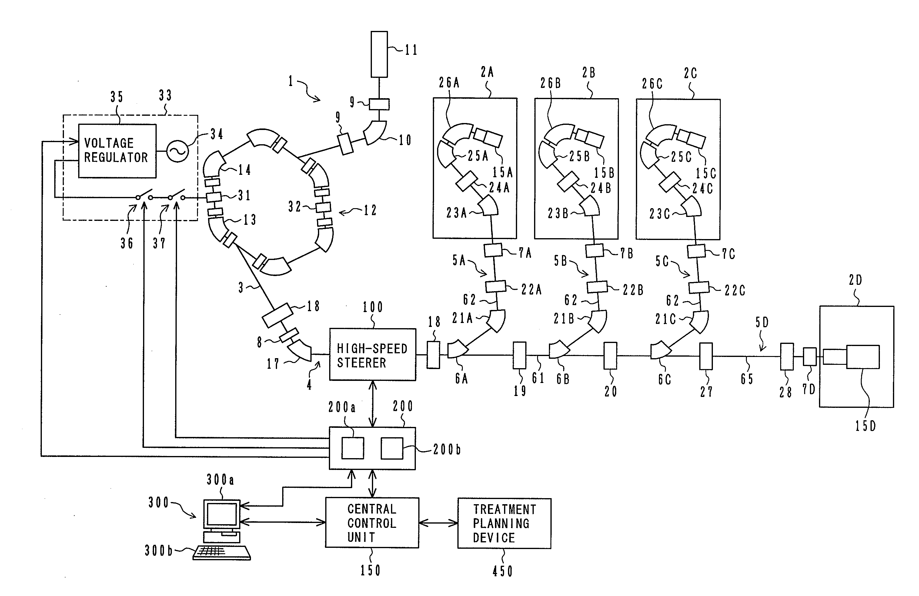
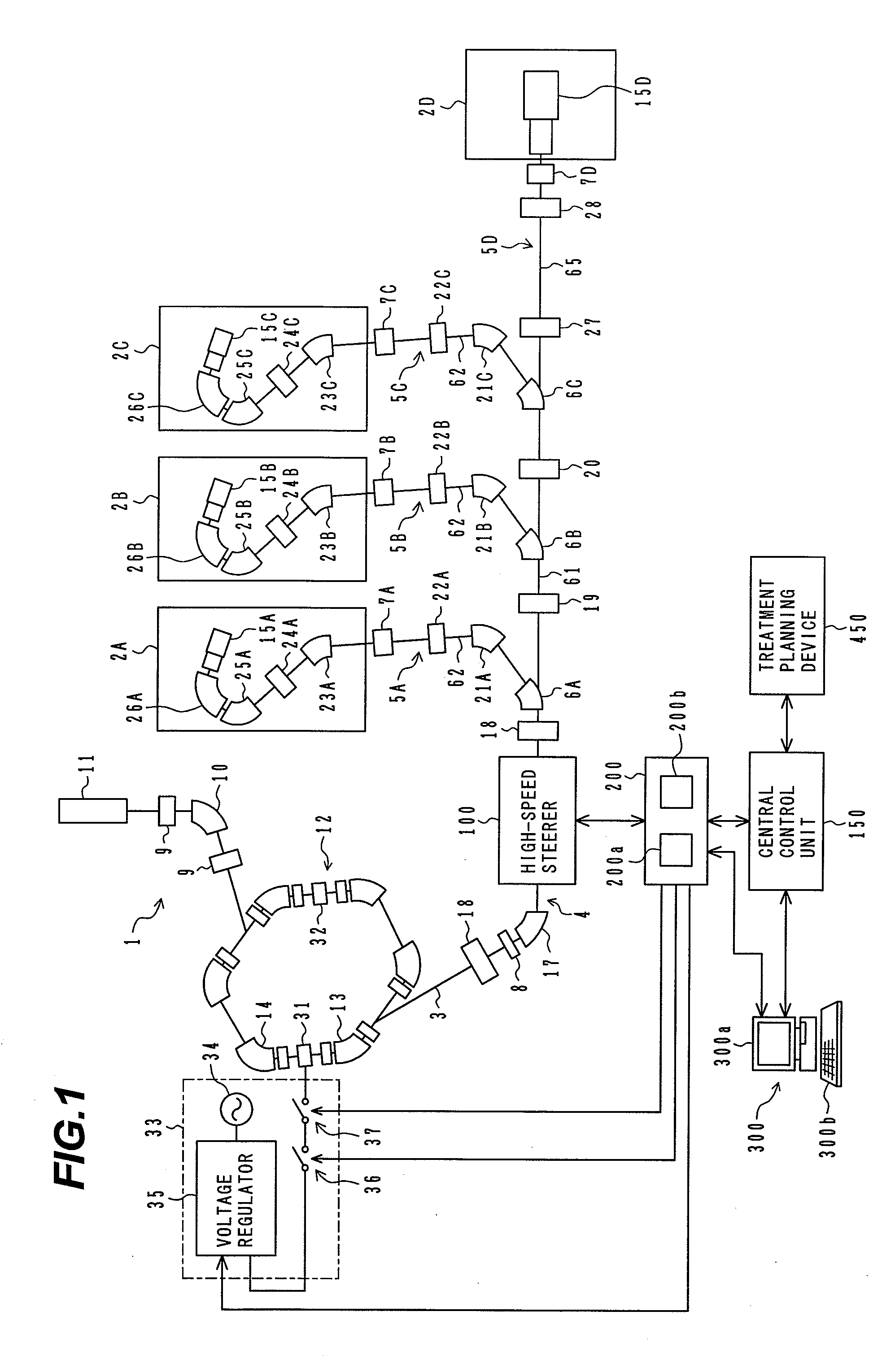
[0032]As shown in FIG. 1, a charged particle beam irradiation system according to the first embodiment includes: a charged-particle (ion) beam generator 1; a first beam transport line 4 provided downstream of the charged-particle beam generator 1; second beam transport lines 5A, 5B, 5C, and 5D, which branch from the first beam transport line 4; switching magnets (path selectors) 6A, 6B, and 6C; and irradiation nozzles 15A, 15B, 15C, and 15D that are irradiation devices. The first beam transport line 4 is a common beam transport line that introduces an ion beam to each of the second beam transport lines 5A, 5B, 5C, and 5D. The second beam transport lines 5A, 5B, 5C, and 5D are provided for the irradiation nozzles 15A, 15B, 15C, and 15D, respectively. The irradiation nozzles 15A, 15B, 15C, and 15D are located in treatment rooms 2A, 2B, 2C, and 2D, respectively. The charged particle beam irradiation system acc...


PUM


Abstract

A charged particle beam irradiation system comprises a high-speed steerer (beam dump device) 100 disposed in a course of a beam transport line 4 through which an ion beam is extracted from a charged-particle beam generator 1. The beam dump device 100 is provided with dose monitoring devices 105, 106 for measuring a dose of an ion beam applied to a beam dump 104 so that the intensity of the ion beam can be measured without transporting the ion beam to irradiation nozzles 15A through 15D. Thus, the system is capable of adjusting the intensity of an ion beam extracted from a synchrotron without operating each component of a beam transport line, and an irradiation nozzle.

Description

BACKGROUND OF THE INVENTION[0001]1. Field of the Invention[0002]The present invention relates to a charged particle beam irradiation system. More particularly the invention relates to a charged particle beam irradiation system that is preferably applied to a particle beam therapy system for treating an affected part by irradiating the affected part with a charged particle beam such as a proton and a carbon ion.[0003]2. Description of the Related Art[0004]A treatment method which irradiates an affected part of a patient (for example, cancer) with a charged particle beam (ion beam) such as a proton and a carbon ion is known. A charged particle beam irradiation system used for the treatment (a particle beam extraction device or a charged particle beam extraction device) includes an ion beam generator. An ion beam accelerated by the ion beam generator passes through a first beam transport line, and a second beam transport line that is disposed in a rotating gantry, and then reaches an i...

Claims


Application Information

Patent Timeline
Patent Type & Authority Applications(United States)
IPC IPC(8): A61N5/00
CPCH05H7/04A61N2005/1087A61N5/1077H05H2007/046
Inventor MORIYAMA, KUNIONAKAYAMA, TAKAHIDENISHIUCHI, HIDEAKI
Owner HITACHI LTD
Why Eureka
Try Eureka