

Resonator
- Summary
- Abstract
- Description
- Claims
- Application Information
AI Technical Summary
Benefits of technology
Problems solved by technology
Method used
Image

Examples
embodiment 1
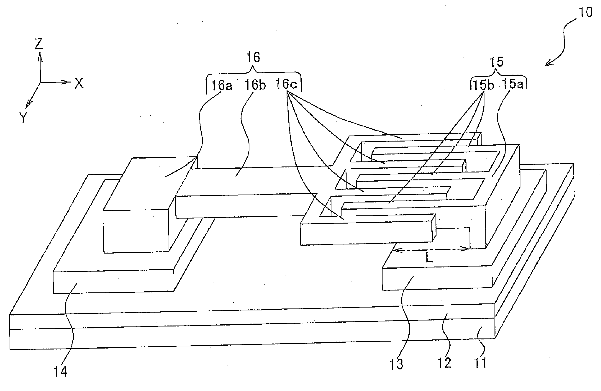
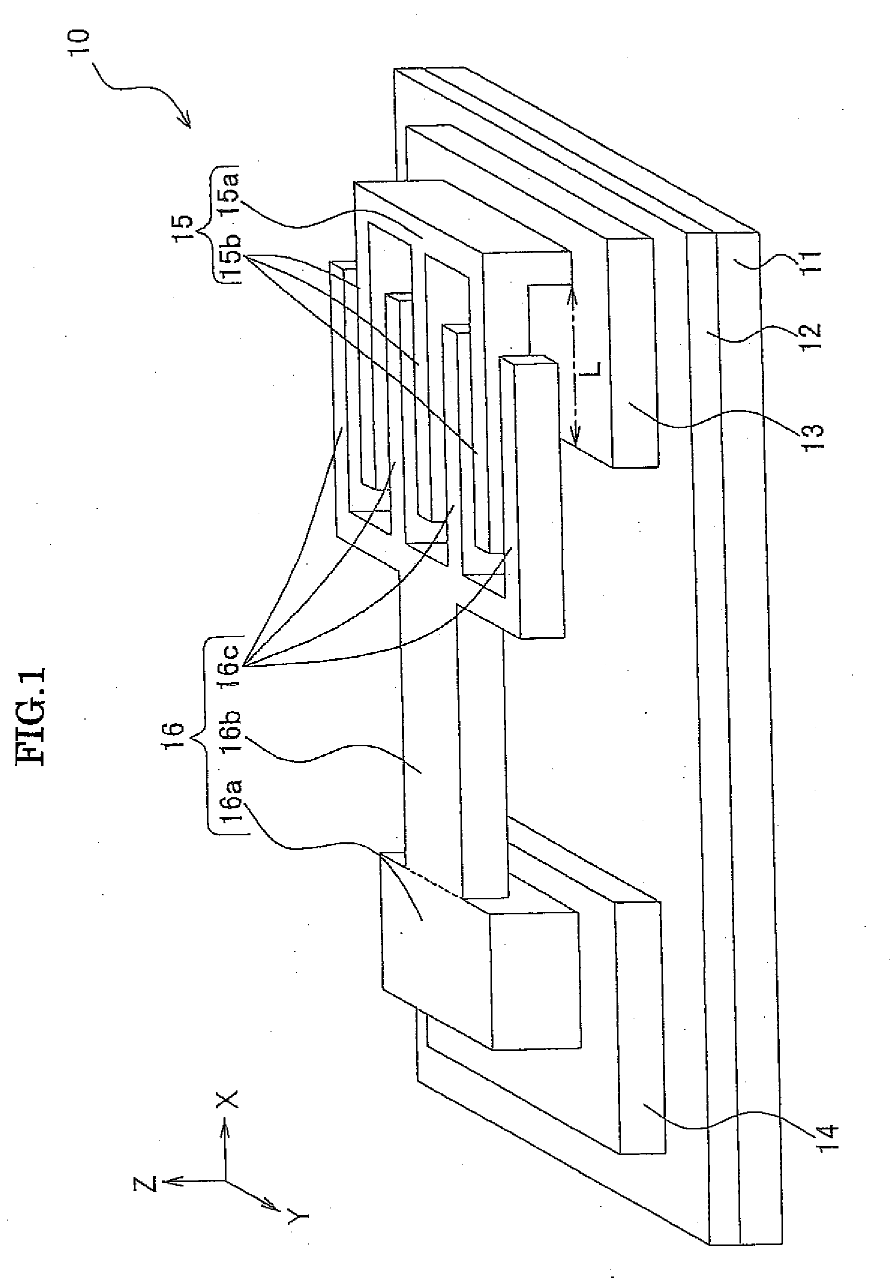
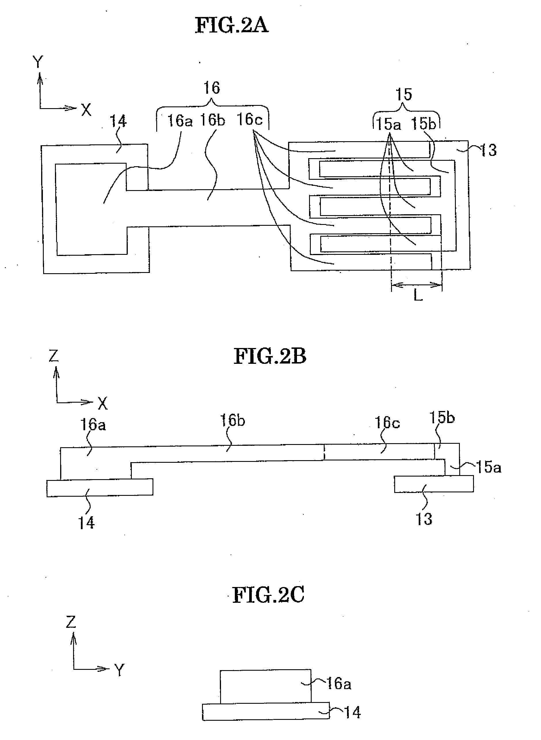
[0038]A resonator 10 according to an embodiment of the present invention will be described in detail with reference to FIGS. 1, 2A, 2B, 2C.
[0039]As shown in FIGS. 1, 2A, 2B, 2C, an SiN film 12, an insulating film, is formed on a silicon substrate 11 so as to cover the upper surface of the silicon substrate 11. Two electrodes, i.e., an output electrode 13 and an input electrode 14 are formed on the SiN film 12. For example, the main surface shape (the shape of the surface crossing a Z axis) of the output electrode 13 and the input electrode 14 is substantially rectangular (longer in a Y-axis direction than in an X-axis direction), and the two electrodes have a predetermined thickness in a Z-axis direction. A predetermined bias voltage is applied between the two electrodes. Further, a predetermined input signal is input to the input electrode 14, and a resonant frequency signal is output from the output electrode 13.
[0040]A fixed electrode (first electrode in the claims) 15 is formed ...
embodiment 2
[0058]An embodiment is the same in configuration as the embodiment 1 except the output electrode, wherein the output electrode is formed of a collection of multiple electrodes so as to enable change in the length in the Z-axis direction of the output electrode and wherein each of the multiple electrodes is connected to switch means. A resonator 50 of this configuration will be described in detail with reference to FIGS. 5, 6. The same reference numerals are used to denote the same or like parts as in the embodiment 1 with description thereof being omitted.
[0059]As shown in FIGS. 5, 6, an output electrode 51 comprises an electrode 51a connected to the support portion 15a of the fixed electrode 15 and five electrodes 51b connected to a switch group 52. Each of the electrodes 51b is connected to one end of a switch 53, and the other end of the switch 53 from the electrode 51b is connected to a reference voltage Vref. The electrode 51a is connected to the reference voltage Vref, not via...
embodiment 3
[0070]An embodiment is the same in configuration as the embodiment 1 except the output electrode and the movable electrode, wherein the electrode portion extending in the minus X-axis direction from the portion connected to the support portion of the output electrode at the lower side is removed and wherein a parallel plate electrode is provided to cover partially the top of the arms of the movable electrode. A resonator 90 having this configuration will be described in detail with reference to FIGS. 8, 9A, 9B, 9C. The same reference numerals are used to denote the same or like parts as in the embodiment 1 with description thereof being omitted.
[0071]As shown in FIGS. 8, 9A, 9B, 9C, an output electrode 91 has no portion extending toward the input electrode 14 (i.e., in the minus X-axis direction) from the portion connected to the support portion 15a at the lower side. Hence, electrostatic force from the output electrode 91 to displace the arms 16c in the Z-axis direction is very sma...
PUM
 Abstract
Description
Claims
Application Information