Vehicle Detecting System

a technology for detecting systems and vehicles, applied in traffic control systems, scene recognition, instruments, etc., can solve the problems of slow processing, inability to easily increase the accuracy of detecting the lateral position, and long processing tim

Active Publication Date: 2009-07-23
SUBARU CORP
View PDF6 Cites 27 Cited by
  • Summary
  • Abstract
  • Description
  • Claims
  • Application Information

AI Technical Summary

Benefits of technology

[0038]In this case, of the right and left lateral positions of the vehicle detected by the lateral-position detecting means and the right and left lateral positions of the vehicle detected by the vehicle detecting means or a sensor, the lateral positions which provide a lateral width closer to the previously detected lateral width of the vehicle are adopted. Hence, the right and left lateral positions of the vehicle corresponding to the actual lateral width of the vehicle can be detected, and the above-described advantages of the present invention can be achieved more reliably.

Problems solved by technology

In this respect, the above-described detection technique using the radar apparatus can, in general, accurately obtain the distance in the front-rear direction, but cannot easily increase the accuracy in detecting the lateral position.
Unfortunately, in the above-described detection system, it is necessary to calculate multiple histograms and to store large amounts of data.
Moreover, since it is necessary to extract values that have time continuity from the data, much time is taken for processing, in other words, processing becomes slow.
Once a wrong position is stored, it is not necessarily easy to correct the position to a right position.
When the brightness pattern of a preceding vehicle or the like changes with time and place, stability of the processing result is not necessarily ensured effectively.
However, for example, when the preceding vehicle runs past an object whose edges are dense, such as the bush, more edges exist in the bush than in the preceding vehicle, and therefore, it is difficult to accurately detect lateral ends of the preceding vehicle.

Method used


Image

  • Vehicle Detecting System
  • Vehicle Detecting System
  • Vehicle Detecting System

Examples


Embodiment Construction

[0056]A vehicle detecting system according to an embodiment of the present invention will be described below with reference to the drawings.

[0057]While stereo images are taken by two cameras serving as an image taking means 2 in this embodiment, for example, the image taking means 2 can be formed by a single camera or three or more cameras. Further, the structure of a vehicle detecting means 11, which will be described below, is not limited to a structure adopted in the embodiment as long as the vehicle detecting means 11 can detect a vehicle, such as a preceding vehicle, from a taken image.

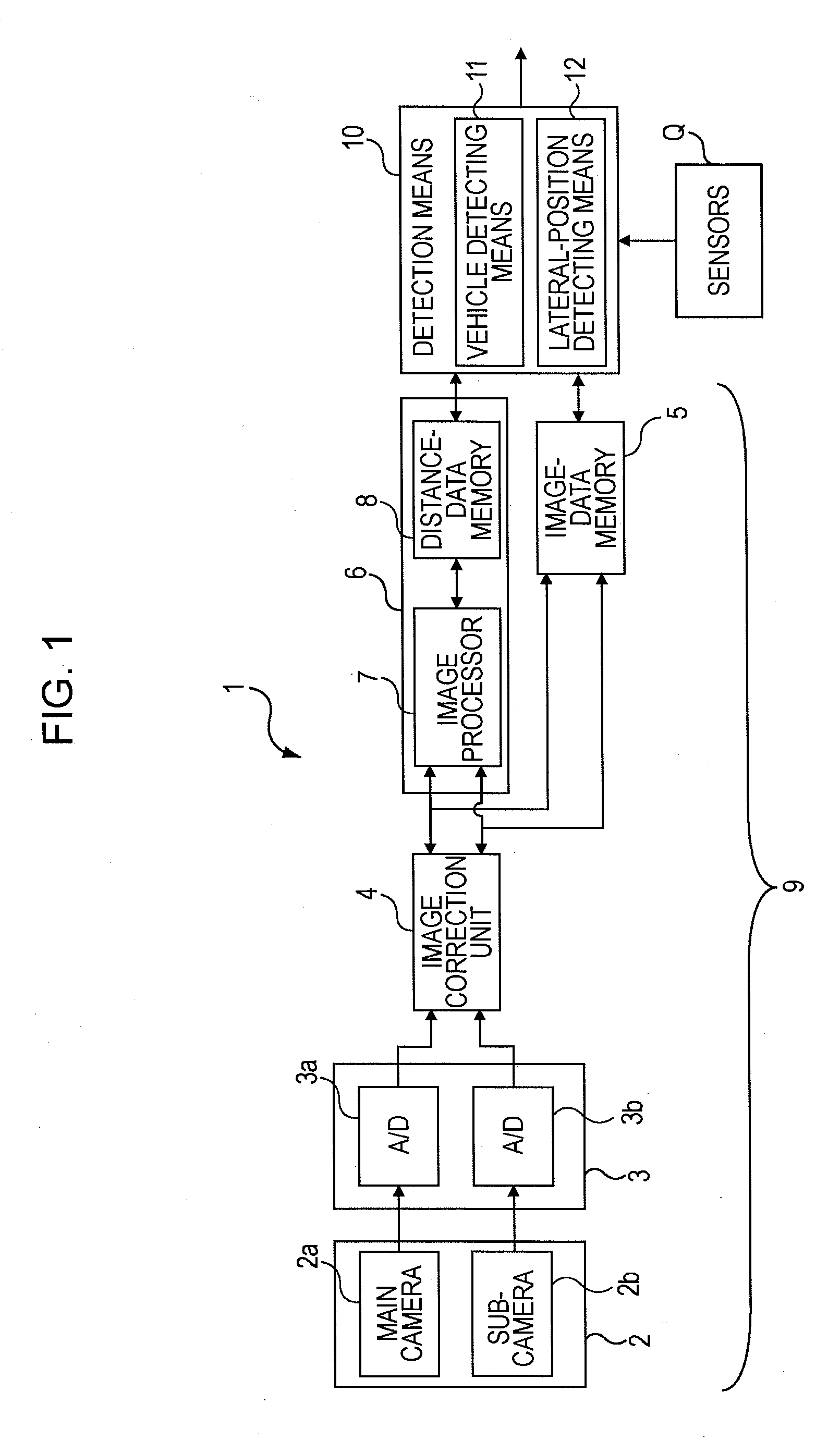
[0058]Referring to FIG. 1, a vehicle detecting system 1 according to the embodiment mainly includes a positional-information collecting means 9 and a detection means 10. The positional-information collecting means 9 includes an image taking means 2, a conversion means 3, and an image processing means 6, etc., and the detecting means 10 includes a vehicle detecting means 11 and a lateral-position ...


PUM


Abstract

A vehicle detecting system includes image taking means for taking an image of the surroundings of a subject vehicle, vehicle detecting means for detecting a vehicle from the taken image, and lateral-position detecting means for detecting a lateral position of the vehicle in the taken image. The lateral-position detecting means vertically divides, into a plurality of sections, a region set in a portion of the taken image in which an image of the vehicle is included or is presumed to be included. The lateral-position detecting means calculates average brightnesses of pixels belonging to pixel columns vertically extending in the sections and having a width corresponding to one pixel or a plurality of number of pixels. The lateral-position detecting means calculates differences in average brightness between pixel columns adjacent in a lateral direction, and detects the lateral position of the vehicle on the basis of absolute values of the differences.

Description

CROSS-REFERENCES TO RELATED APPLICATIONS[0001]The disclosure of Japanese Patent Application No. 2008-011467 filed on Jan. 22, 2008 including the specification, drawings and abstract is incorporated herein by reference in its entirety.BACKGROUND OF THE INVENTION[0002]1. Field of the Invention[0003]The present invention relates to vehicle detecting systems, and more particularly, to a vehicle detecting system including an image taking means that takes images for detecting at least a vehicle.[0004]2. Description of the Related Art[0005]In recent years, techniques of detecting objects existing around a vehicle, such as a car, by analyzing an image taken by an image taking means, such as a charge coupled device (CCD) camera, or analyzing reflected waves of radio waves emitted from a radar apparatus, have been developed (for example, see Japanese Unexamined Patent Application Publication No. 2006-140636). These techniques are applied to safe driving technologies for vehicles. For safe dri...

Claims


Application Information

Patent Timeline
Patent Type & Authority Applications(United States)
IPC IPC(8): G08G1/04
CPCG06K9/00805G08G1/16G08G1/166G08G1/167G06V20/58
Inventor SAITO, TORU
Owner SUBARU CORP
Why Eureka
Try Eureka