Tool system

a tool system and tool technology, applied in the field of tool systems, can solve the problems of disadvantageously affecting the machining accuracy, impairing the machining accuracy, and the known tool system cannot adequately meet the requirement, and achieve the effect of reducing the cost of production, rigidity and security against large loads

Active Publication Date: 2009-07-23
HARTMETALL WERKZEUGFAB PAUL HORN
View PDF18 Cites 8 Cited by
  • Summary
  • Abstract
  • Description
  • Claims
  • Application Information

AI Technical Summary

Benefits of technology

[0008]With regard thereto, the object of the invention is to make available a tool system that, realized inexpensively, ensures that the cutting tool is fixed to the holder in a manner that is particularly rigid and secure against large loads.

Problems solved by technology

The known tool systems do not adequately fulfill this requirement.
It is not possible in such a manner to preclude the occurrence of static redundancy in the fixing of the tool in the receiver, which could impair the machining accuracy.
In addition, owing to the multiplicity of cutting tools used, a particularly stiff overall design of the tool system is almost unachievable with the special arcuate mounting provided for said cutting tools, which again can disadvantageously affect the machining accuracy.

Method used


Image

  • Tool system
  • Tool system
  • Tool system

Examples


Embodiment Construction

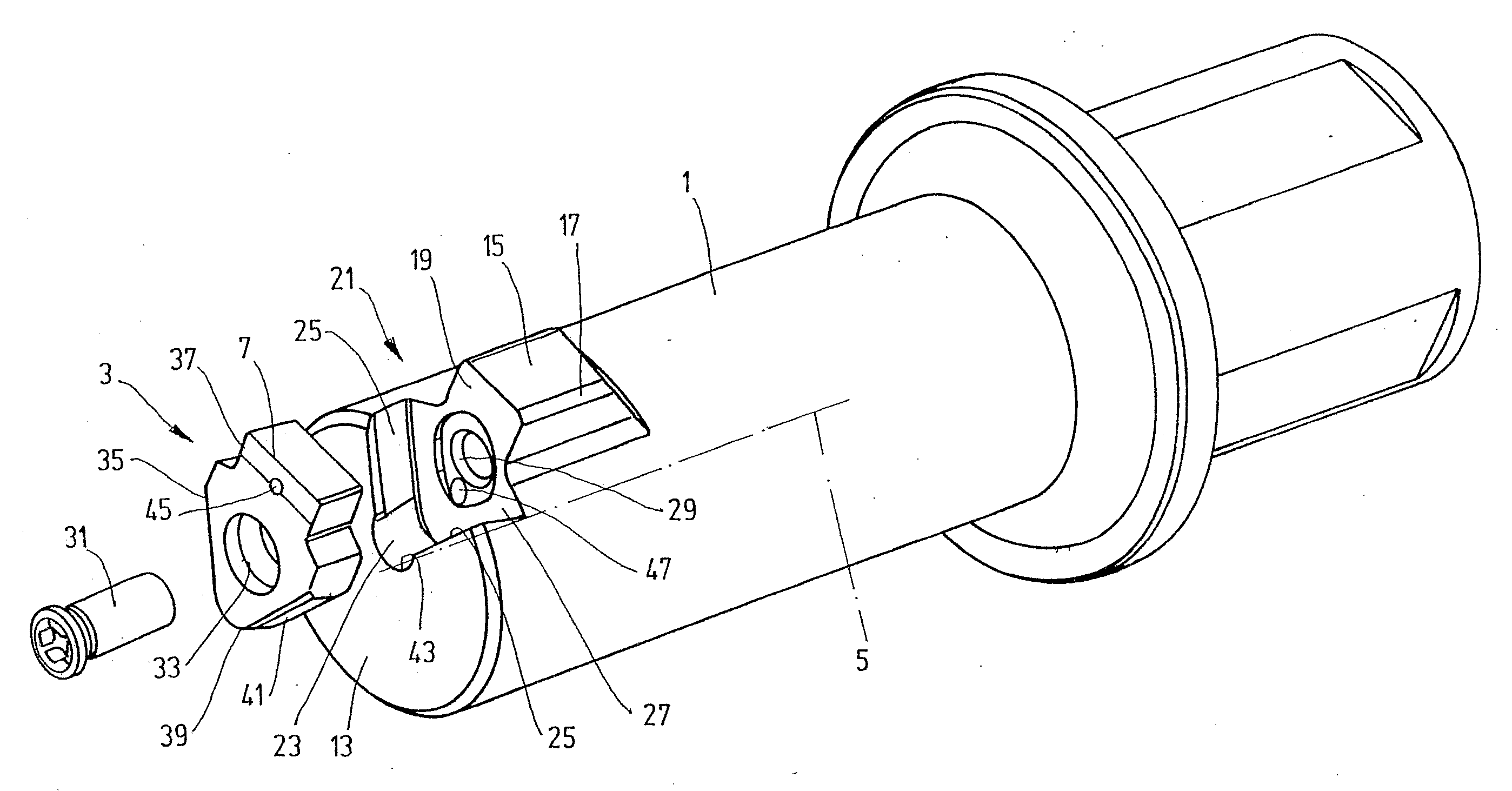
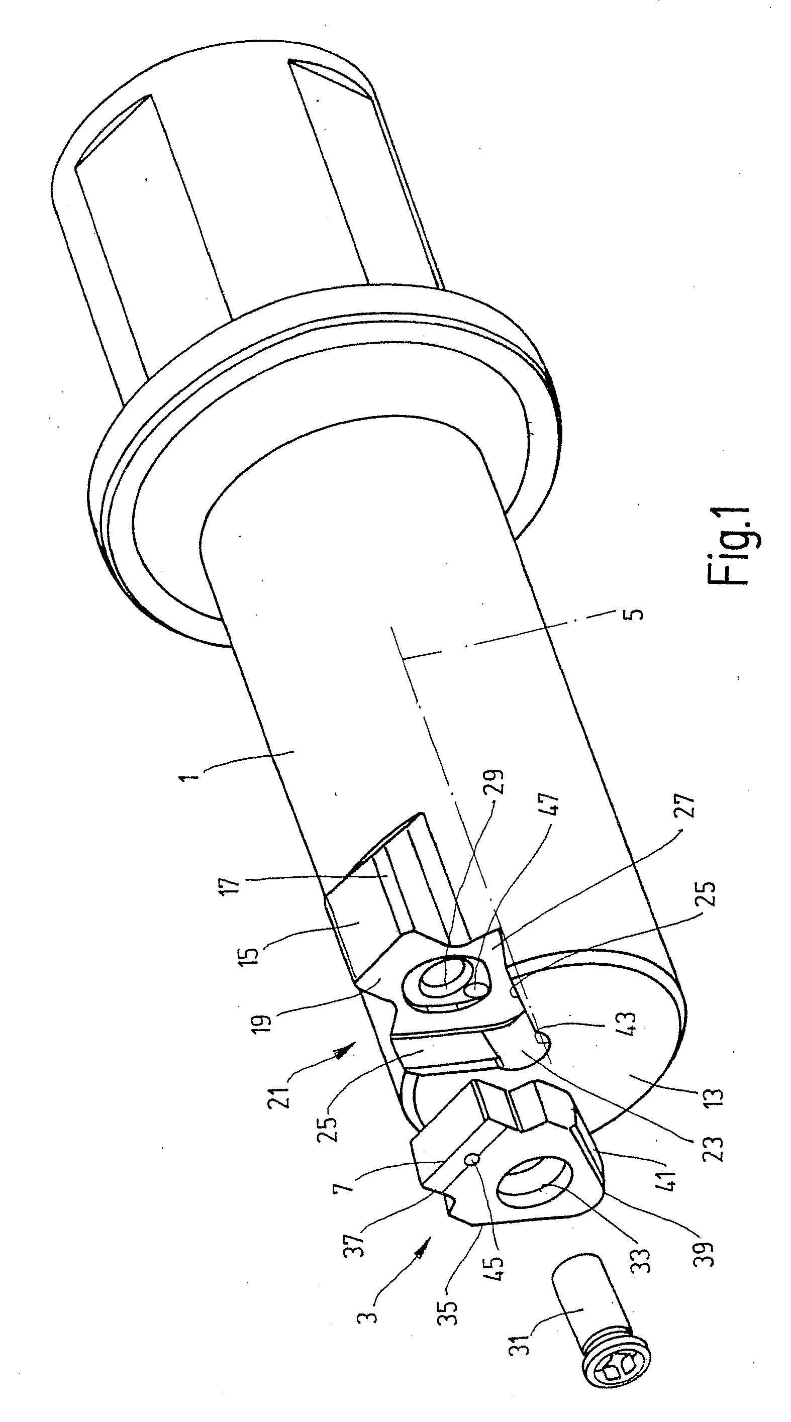
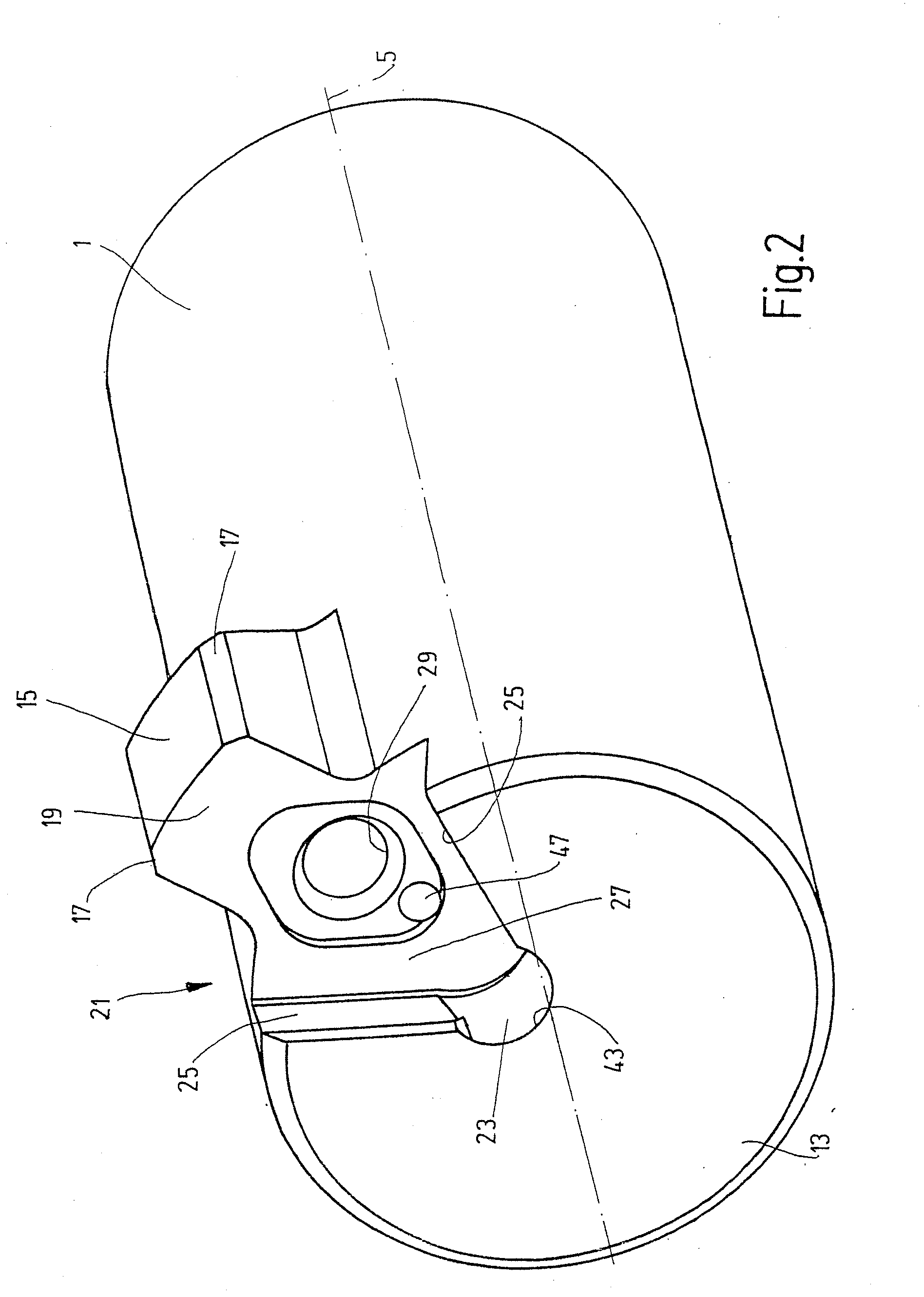
[0025]The invention is explained in the following with reference to an exemplary embodiment in which the tool system constitutes a broaching tool, the holder 1, with the cutting tool 3 fixed to the front thereof, being moved in the direction of the holder longitudinal axis 5, in order to perform broaching machining on a workpiece, not shown, by means of a main cutter 7 of the cutting tool 3, the main cutter 7 extending perpendicularly in relation to the longitudinal axis 5. In the case of use as a broaching tool, a cutting or working force that is directed mostly along the longitudinal axis 5 is effective during the working operation. In the case of an alternative application of the tool system for turning machining or drilling machining, in which machining operations a chip-removing operation can be effected at cutters 9 and / or 11 located close to the main cutter 7, see FIG. 3, a force component is likewise produced along the longitudinal axis 5.

[0026]FIGS. 1 and 2 illustrate the s...


PUM

PropertyMeasurementUnit
included angleaaaaaaaaaa
lengthaaaaaaaaaa
circumferenceaaaaaaaaaa

Abstract

A tool system comprising a holder and a cutting tool having a tool cutting edge and a fixing part, wherein the tool cutting edge projects by a predeterminable projecting length beyond the holder for a machining operation, is characterized in that the holder is provided at the outer circumference with a supporting part which projects in the direction of the projecting length of the tool cutting edge and forms a supporting surface for at least partial abutment of the cutting tool.

Description

CROSS-REFERENCE TO RELATED APPLICATIONS[0001]This is a continuation application of international patent application PCT / EP2007 / 006661, filed on Jul. 27, 2007, designating the United States and published in German as WO 2008 / 014932 A1, which claims priority to German application No. 10 2006 035 182, filed on Jul. 29, 2006, the entireties of which are hereby incorporated by reference.BACKGROUND OF THE INVENTION[0002]1. Field of the Invention[0003]The invention relates to a tool system comprising a holder and a cutting tool that has a tool cutter and a fixing part.[0004]2. Related Prior Art[0005]Known in the prior art are tool systems for metal machining that, acting in combination with a rotating drive spindle or a non-rotating machine support, constitute a rotating or non-rotating machining tool. For example, DE 34 48 086 C2 discloses a tool for internal machining. When combined with a machine tool that imparts a translational motion to the holder, such tool systems can also be used ...

Claims


Application Information

Patent Timeline
Patent Type & Authority Applications(United States)
IPC IPC(8): B26D1/25
CPCB23B27/10Y10T407/23B23B29/04B23B2200/0423B23B2200/123B23B2200/125B23B2200/321B23B2200/323B23B2205/12B23B2250/12B23D13/00Y10T408/455Y10T407/14Y10T407/2274Y10T407/1934Y10T407/192Y10T407/1924Y10T407/25B23B27/1614
Inventor NOUREDDINE, HASSAN
Owner HARTMETALL WERKZEUGFAB PAUL HORN
Why Eureka
Try Eureka