Titanate and metal interconnects for solid oxide fuels cells

Inactive Publication Date: 2009-07-23
SAINT GOBAIN CERAMICS & PLASTICS INC
View PDF14 Cites 9 Cited by
  • Summary
  • Abstract
  • Description
  • Claims
  • Application Information

AI Technical Summary

Benefits of technology

[0010]It is believed that the doped M-titanates (e.g., MTiO3) in the invention, particularly, n-doped M-titanates, such as n-doped SrTiO3 or CaTiO3, exhibit less oxygen vacancy formation during operation of SOFCs, as compared to conventional p-doped LaCrO3, thereby limiting or eliminating lattice expansion problems associated with conventional p-doped LaCrO3. In addition, the doped M-titanates can function as an effective oxidation barrier to thereby extend operation life of SOFCs.

Problems solved by technology

Interconnects are one of the critical issues limiting commercialization of solid oxide fuel cells.
However, oxidation of metal interconnects during operation, thereby forming metal oxides, such as Cr2O3, and subsequent migration of metals of the metal oxides (e.g., chromium migration) to an electrode layer and / or electrode-electrolyte interface is one of the primary mechanisms leading to performance degradation in solid oxide fuel cells.
While metal interconnects are relatively easy to fabricate and process, they generally suffer from high power degradation rates (e.g. 10% / 1,000 h) partly due to formation of metal oxide, such as Cr2O3, at an interconnect-anode / cathode interface during operation.
However, doped LaCrO3 generally suffers from dimensional changes, such as warping or some other forms of distortion, and consequent seal failures in reducing conditions.
Another issue related to LaCrO3 is its relatively low sinterability.

Method used


Image

  • Titanate and metal interconnects for solid oxide fuels cells
  • Titanate and metal interconnects for solid oxide fuels cells
  • Titanate and metal interconnects for solid oxide fuels cells

Examples


Embodiment Construction

[0015]The foregoing will be apparent from the following more particular description of example embodiments of the invention, as illustrated in the accompanying drawings in which like reference characters refer to the same parts throughout the different views. The drawing is not necessarily to scale, emphasis instead being placed upon illustrating embodiments of the present invention.

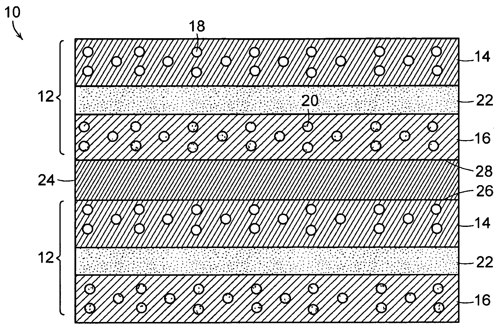
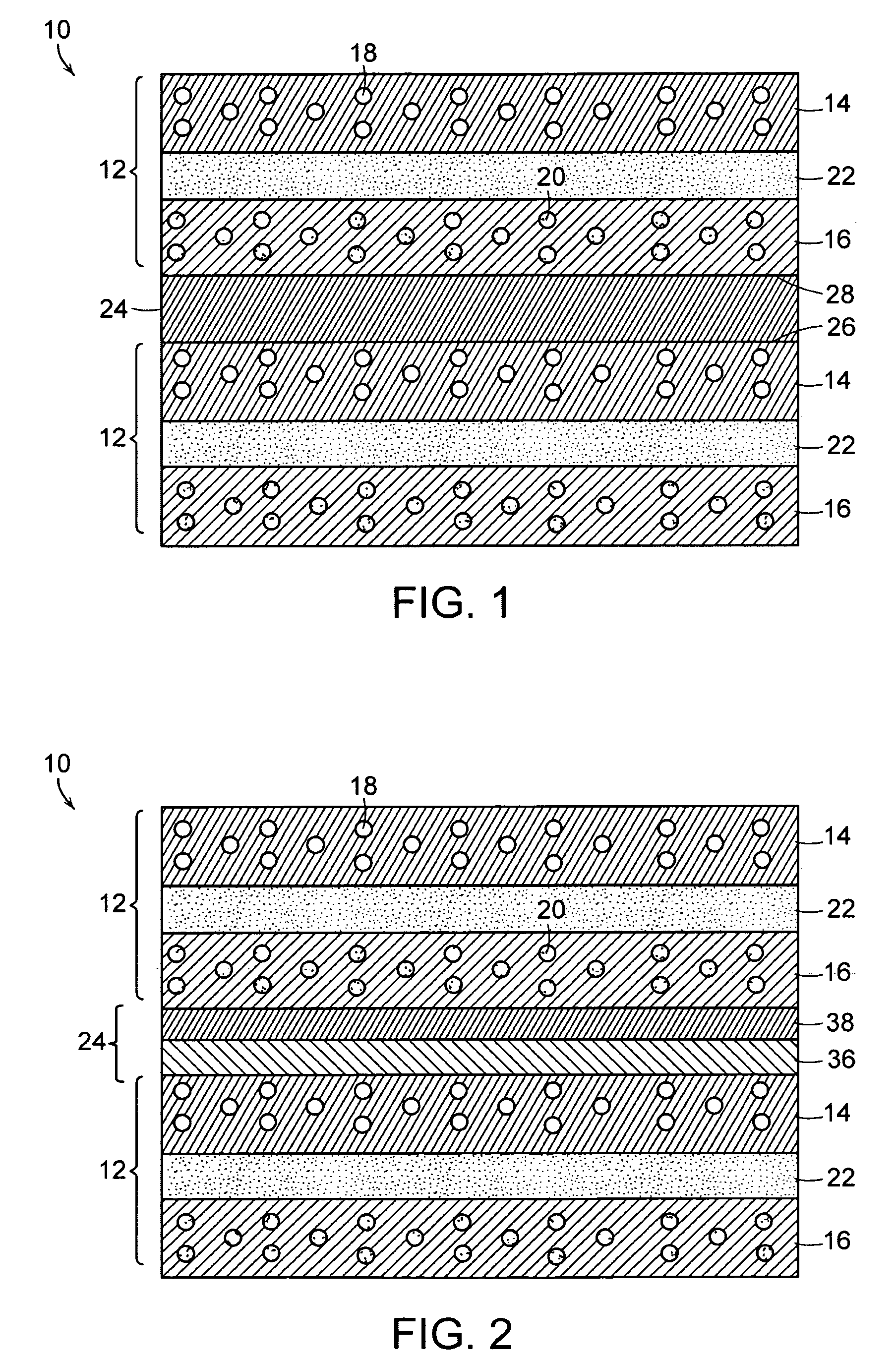
[0016]FIG. 1 shows fuel cell 10 of the invention. Fuel cell 10 includes a plurality of sub-cells 12. Each sub-cell 12 includes first electrode 14 and second electrode 16. Typically, first and second electrodes 14 and 16 are porous. In fuel cell 10, first electrode 14 at least in part defines a plurality of first gas channels 18 in fluid communication with a source of oxygen gas, such as air. Second electrode 16 at least in part defines a plurality of second gas channels 20 in fluid communication with a fuel gas source, such as H2 gas or a natural gas which can be converted into H2 in situ at second elect...


PUM

PropertyMeasurementUnit
Thicknessaaaaaaaaaa
Thicknessaaaaaaaaaa
Thicknessaaaaaaaaaa

Abstract

A solid oxide fuel cell (SOFC) includes a plurality of sub-cells. Each sub-cell includes a first electrode in fluid communication with a source of oxygen gas, a second electrode in fluid communication with a source of a fuel gas, and a solid electrolyte between the first electrode and the second electrode. The SOFC further includes an interconnect between the sub-cells. In one embodiment, the SOFC has a first surface in contact with the first electrode of each sub-cell and a second surface that is in contact with the second electrode of each sub-cell; and the interconnect consists essentially of a doped M-titanate based perovskite, wherein M is an alkaline earth metal. In another embodiment, the interconnect includes a first layer in contact with the first electrode of each sub-cell, and a second layer in contact with the second electrode of each sub-cell. The first layer includes an electrically conductive material selected from the group consisting of an metal, a metal alloy and a mixture thereof. The second layer includes a doped M-titanate based perovskite, wherein M is an alkaline earth metal. A solid oxide fuel cell described above is formed by connecting each of the sub-cells with an interconnect described above.

Description

RELATED APPLICATIONS[0001]This application claims the benefit of U.S. Provisional Application Nos. 60 / 877,503 and 60 / 877,504, both filed Dec. 28, 2006. The entire teachings of these applications are incorporated herein by reference.BACKGROUND[0002]A fuel cell is a device that generates electricity by a chemical reaction. Among various fuel cells, solid oxide fuel cells use a hard, ceramic compound of metal (e.g., calcium or zirconium) oxide as an electrolyte. Typically, in the solid oxide fuel cells, an oxygen gas, such as O2, is reduced to oxygen ions (O2−) at the cathode, and a fuel gas, such as H2 gas, is oxidized with the oxygen ions to from water at the anode.[0003]Interconnects are one of the critical issues limiting commercialization of solid oxide fuel cells. Currently, most companies and researchers working with planar cells are using coated metal interconnects. For example, ferritic stainless steel based metal interconnects, such as Crofer 22 APU, and powder metallurgy for...

Claims


Application Information

Patent Timeline
IPC IPC(8): H01M8/10H01M8/00
CPCH01M8/0206H01M8/0217H01M8/0228Y02E60/50Y10T29/49108H01M8/0202H01M8/0223H01M8/0215H01M8/0208H01M8/02H01M8/12
Inventor NARENDAR, YESHWANTH
Owner SAINT GOBAIN CERAMICS & PLASTICS INC
Why Eureka
Try Eureka