
Non-magnetic toner

Active Publication Date: 2009-07-23
CANON KK
View PDF12 Cites 18 Cited by
  • Summary
  • Abstract
  • Description
  • Claims
  • Application Information

AI Technical Summary

Benefits of technology

[0019]The present invention aims to solve the above-mentioned problems of the conventional art.(1) That is, an object of the present invention is to provide a non-magnetic toner capable of providing a high-resolution, high-definition image.(2) Another object of the present invention is to provide a non-magnetic toner excellent in low-temperature fixability and capable of providing an image having a gloss value and an image density needed for bringing the quality of the image close to that of a photograph or print while achieving the object in the above section (1).(3) Still another object of the present invention is to provide a non-magnetic toner capable of suppressing the occurrence of the contamination of a member irrespective of an environment under which image output is performed and excellent in durability while achieving the object in the above section (1)(4) Still another object of the present invention is to provide a non-magnetic toner showing quick rise-up of charging and having a sharp charge quantity distribution, high developing performance, and high transferring performance.(5) Still another object of the present invention is to provide a non-magnetic toner capable of suppressing the occurrence of blocking when the toner is left to stand at high temperatures and excellent in storage stability.
[0022]The non-magnetic toner of the present invention has low-temperature fixability, and each particle of the toner has high toughness. Accordingly, the toner hardly causes the contamination of a member, shows a small change in its triboelectric charging characteristic, and is excellent in long-term durability. In addition, the toner is excellent in transferring performance, and can provide a high-definition, high-quality image.

Problems solved by technology

However, in extreme cases, merely lowering the Tg or average molecular weight of the binder resin to be used in the toner impairs the storage stability of the toner to such an extent that an image cannot be obtained.
In addition, particularly at the time of high-speed development or in the case of a non-magnetic, one-component developing system suitably applicable to a small apparatus with a low running cost, the toner is apt to collapse owing to a reduction in strength of the toner, so the contamination of a member due to the melt adhesion of the toner or to the exudation of a wax in the toner is apt to occur.
As a result, it may become impossible to achieve the following object: an image-forming apparatus with a long lifetime and a low running cost.
That is, when improving the fixing characteristic of the toner is simply attempted, the developing characteristic of the toner is impaired.
In contrast, when the developing characteristic precedes the fixing characteristic, it may be impossible to improve the fixing characteristic.
Although a reduction in average particle diameter of the toner is indeed effective means particularly from the viewpoints of improvements in definition and quality of an image as described above, the means unfortunately promotes the contamination of a member due to the melt adhesion of the toner or to the exudation of the wax, thereby making it additionally difficult to achieve compatibility between the low-temperature fixability and developing characteristic of the toner.
However, each conventionally proposed technology is still susceptible to improvement in terms of the following point: while good fixing performance and high gloss are maintained, such damage to toner as described above is alleviated, and, for example, even when an increase in temperature inside a contact developing system due to continuous paper feeding in the system occurs, stable developing performance is obtained over a long time period.

Method used


Image

  • Non-magnetic toner
  • Non-magnetic toner
  • Non-magnetic toner

Examples


example 1

Preparation of Aqueous Dispersion Medium

[0309]

Water350partsTricalcium phosphate3parts

[0310]The temperature of the mixture of the above components was held at 60° C. while the mixture was stirred with a high-speed stirring apparatus TK-homomixer at a speed of 12,000 rpm, whereby an aqueous dispersion medium was prepared.

(Preparation of Polymerizable Monomer Composition 1)

[0311]

Styrene65partsC.I. Pigment Blue 15:35partsNegative charge control agent (aluminum1part3,5-di-t-butyl salicylate compound)

[0312]The above prescriptions were dispersed with an Attritor at normal temperature for 5 hours, whereby a monomer mixture 1 was prepared.

[0313]Subsequently, the monomer mixture 1 was loaded into a stirring tank the temperature of which could be controlled, and its temperature was increased to 60° C.

[0314]Next, 10 parts of a Fischer-Tropsch wax (having the highest endothermic peak at 75° C.) were loaded into the above stirring tank, and the resultant mixture was continuously stirred for an ad...

example 2

[0357]Cyan Toner No. 2 was obtained in the same manner as in Example 1 except that the amount in which the polar resin was used was changed to 40 parts. Table 1 shows the physical properties of the toner, and Table 2 shows the results of the evaluation.

example 3

[0358]Cyan Toner No. 3 was obtained in the same manner as in Example 1 except that the amount in which the polar resin was used was changed to 10 parts. Table 1 shows the physical properties of the toner, and Table 2 shows the results of the evaluation.


PUM


Abstract

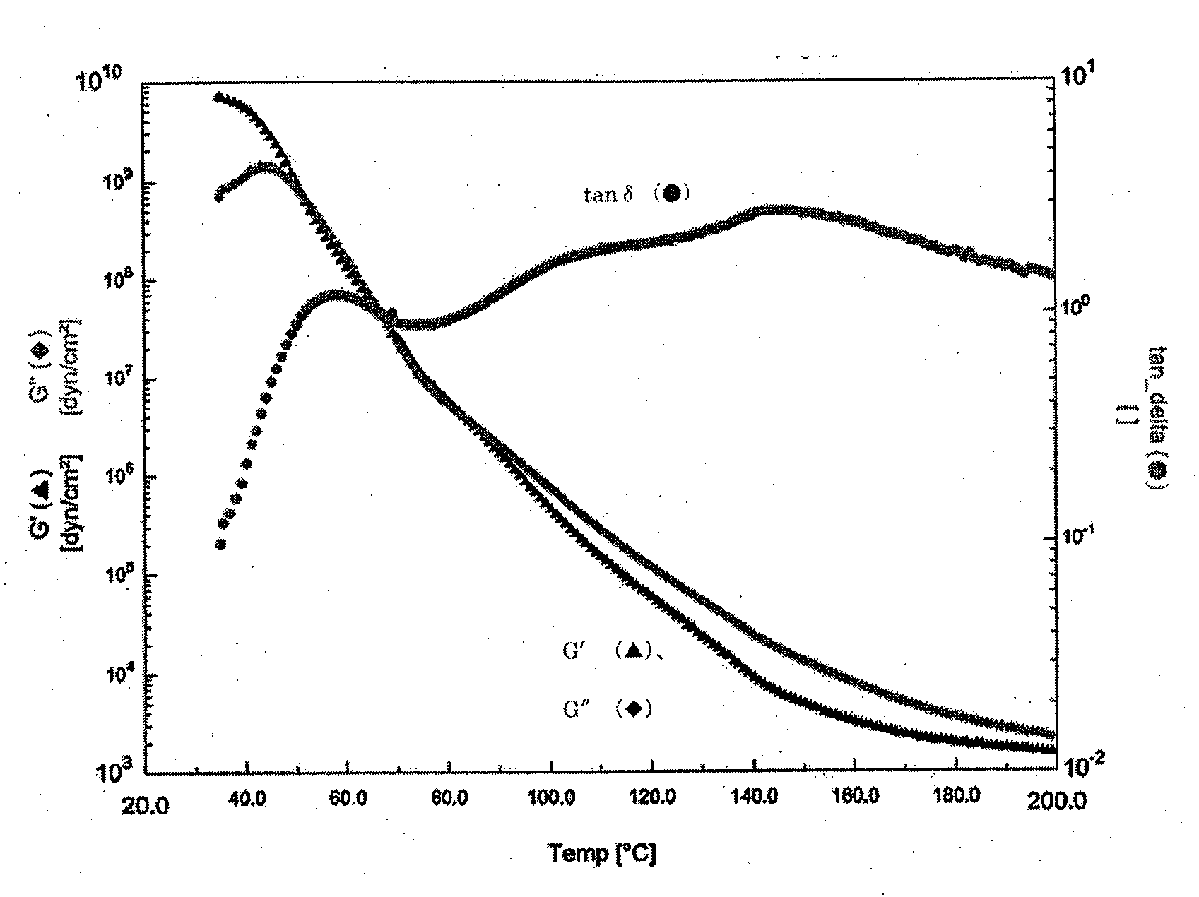
Provided is anon-magnetic toner including toner particles each containing at least a binder resin, a colorant, and a wax component, and an inorganic fine powder, in which: (1) when a temperature in a temperature range of 50 to 80° C. at which a loss tangent (tan δ) shows a maximum is represented by T1, a storage elastic modulus of the toner at the temperature T1 (G′(T1)) satisfies a relationship of 5.00×10⁷≦G′(T1)≦1.00×10⁹ (dN / m2); (2) a continuous temperature range with a width of 15° C. or more in which the loss tangent (tan δ) is 0.80 to 2.00 is present in the temperature range of 50 to 80° C.; and (3) the loss tangent (tan δ) is 1.00 or more in a temperature range of 120 to 160° C.

Description

BACKGROUND OF THE INVENTION[0001]1. Field of the Invention[0002]The present invention relates to a non-magnetic toner for use in a recording method using an electrophotographic method, an electrostatic recording method, a toner jet method, or the like.[0003]2. Description of the Related Art[0004]In recent years, it has been strongly demanded that an electrophotographic apparatus such as a printer apparatus perform printing at an increased speed and be run at a reduced cost while achieving improvements in definition and quality of an image, and energy savings to an extent larger than the conventional one.[0005]In association with such demand, characteristics requested of toner have become more and more sophisticated, and have covered a broader spectrum. Accordingly, attempts based on various viewpoints have been made on the development of the toner.[0006]From the viewpoints of improvements in definition and quality of an image, a reduction in size of each particle of toner has been d...

Claims


Application Information

Patent Timeline
IPC IPC(8): G03G9/087G03G9/00
CPCG03G9/0806G03G9/0815G03G9/0819G03G9/0827G03G9/08791G03G9/09733G03G9/08797G03G9/09357G03G9/09385G03G9/09392G03G9/09708G03G9/08795
Inventor YOSHIZAKI, KAZUMIINABA, KOJIKATSUTA, YASUSHI
Owner CANON KK
Learn More