

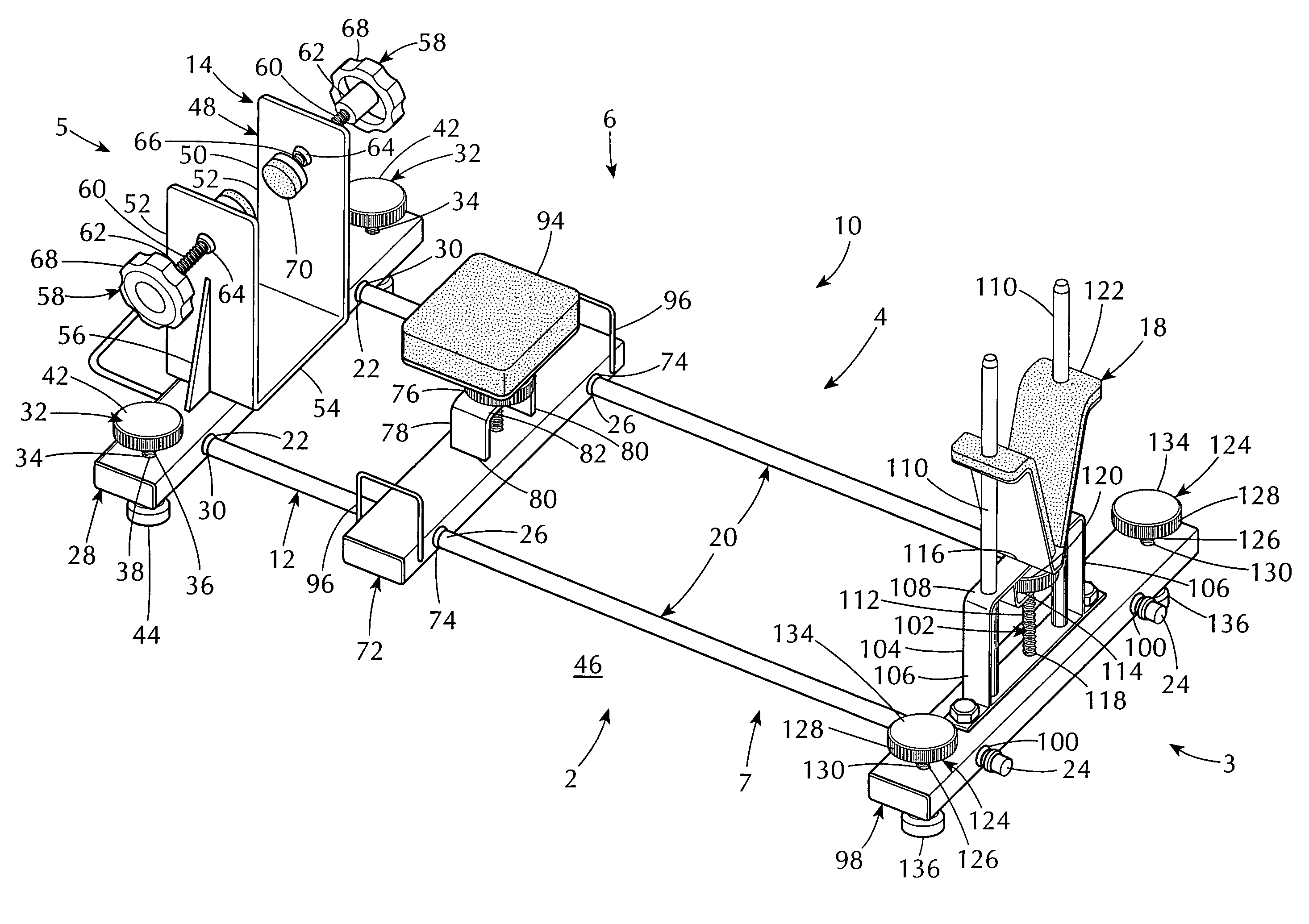
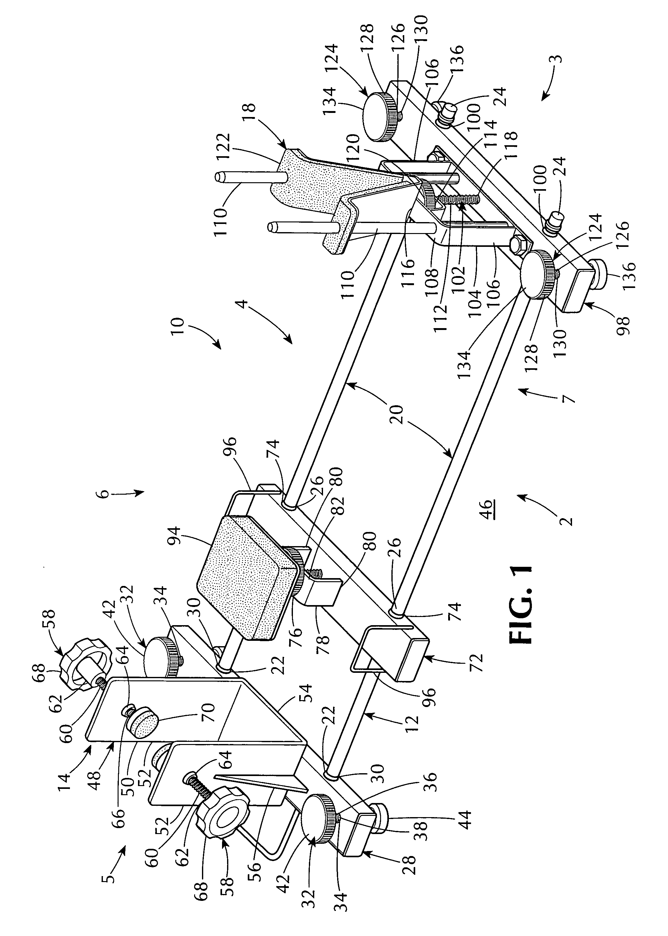
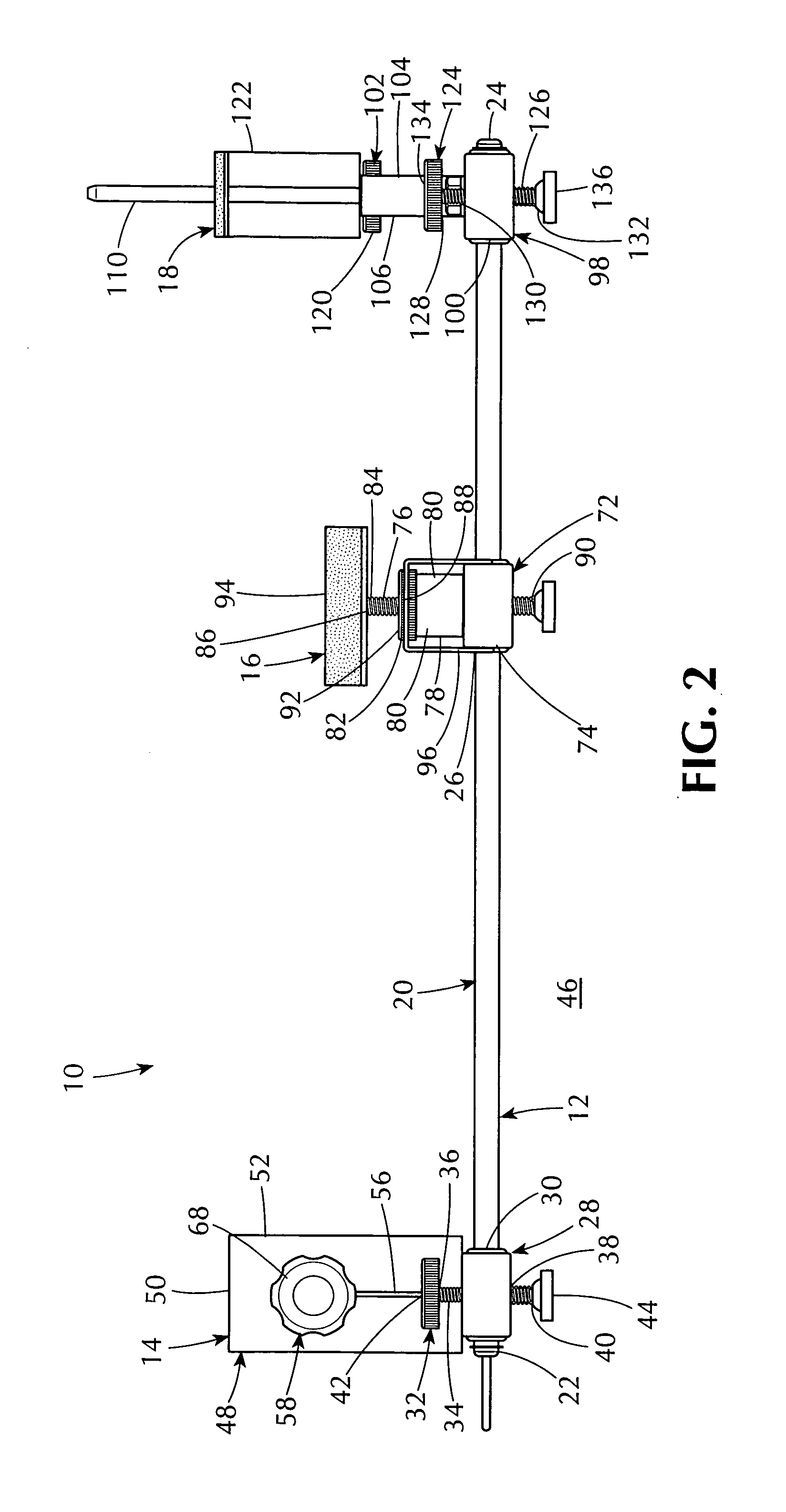
Rest for cleaning a rifle and for sighting a scope, a stock, and a bore of the rifle
a technology for cleaning rifles and rifle bores, applied in the field of rifle rests, can solve the problems of improper mounting of telescopic sights, poor function of scopes, and inability to meet the needs of sportsmen, and achieve the effects of not being suitable, not being convenient to use, and being easy to clean
- Summary
- Abstract
- Description
- Claims
- Application Information
AI Technical Summary
Benefits of technology
Problems solved by technology
Method used
Image

Examples
Embodiment Construction
A. General.
[0163]Referring now to the figures, in which like numerals indicate like parts, and particularly to FIGS. 1-7, which are, respectively, a diagrammatic perspective view of the rest of the embodiments of the present invention for cleaning a rifle (not shown) and for sighting a scope (not shown), a stock (not shown), and a bore (not shown) of the rifle (not shown), a diagrammatic right elevational view taken generally in the direction of ARROW 2 in FIG. 1, a diagrammatic front end view taken generally in the direction of ARROW 3 in FIG. 1, a diagrammatic left elevational view taken generally in the direction of ARROW 4 in FIG. 1, a diagrammatic back end view taken generally in the direction of ARROW 5 in FIG. 1, a diagrammatic top plan view taken generally in the direction of ARROW 6 in FIG. 1, and a diagrammatic bottom plan view taken generally in the direction of ARROW 7 in FIG. 1, the rest of the embodiments of the present invention is shown generally at 10 for cleaning a...
PUM
 Abstract
Description
Claims
Application Information