Shared flow thermal management system

a technology of thermal management system and shared flow, which is applied in the direction of machines/engines, mechanical equipment, turbine/propulsion fuel heating, etc., can solve the problems of reducing engine efficiency, affecting engine efficiency, and affecting engine efficiency

Active Publication Date: 2009-07-30
RTX CORP
View PDF31 Cites 104 Cited by
  • Summary
  • Abstract
  • Description
  • Claims
  • Application Information

AI Technical Summary

Problems solved by technology

Conventional TMS heat exchanger locations may partially interrupt the engine thrust airflow and reduce engine efficiency.
This location may also introduce mixing losses which may further detract from engine efficiency.

Method used


Image

  • Shared flow thermal management system
  • Shared flow thermal management system
  • Shared flow thermal management system

Examples


Embodiment Construction

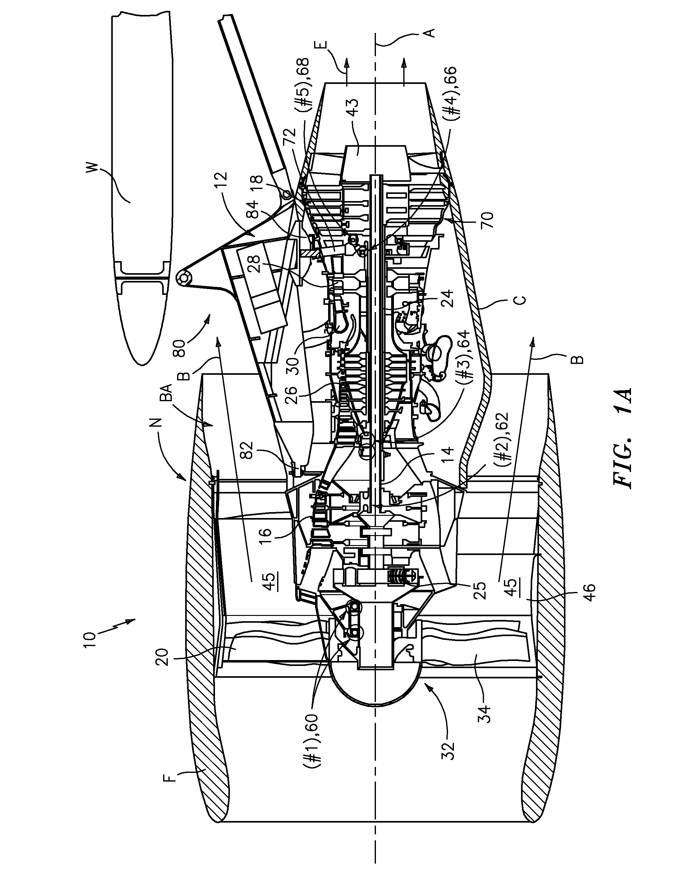
[0013]FIG. 1A illustrates a general partial fragmentary schematic view of a gas turbine engine 10 suspended from an engine pylon structure 12 within an engine nacelle assembly N as is typical of an aircraft designed for subsonic operation. It should be understood that although a particular component arrangement is disclosed in the illustrated embodiment, various pylon structures 12 and nacelle assemblies N will benefit herefrom.

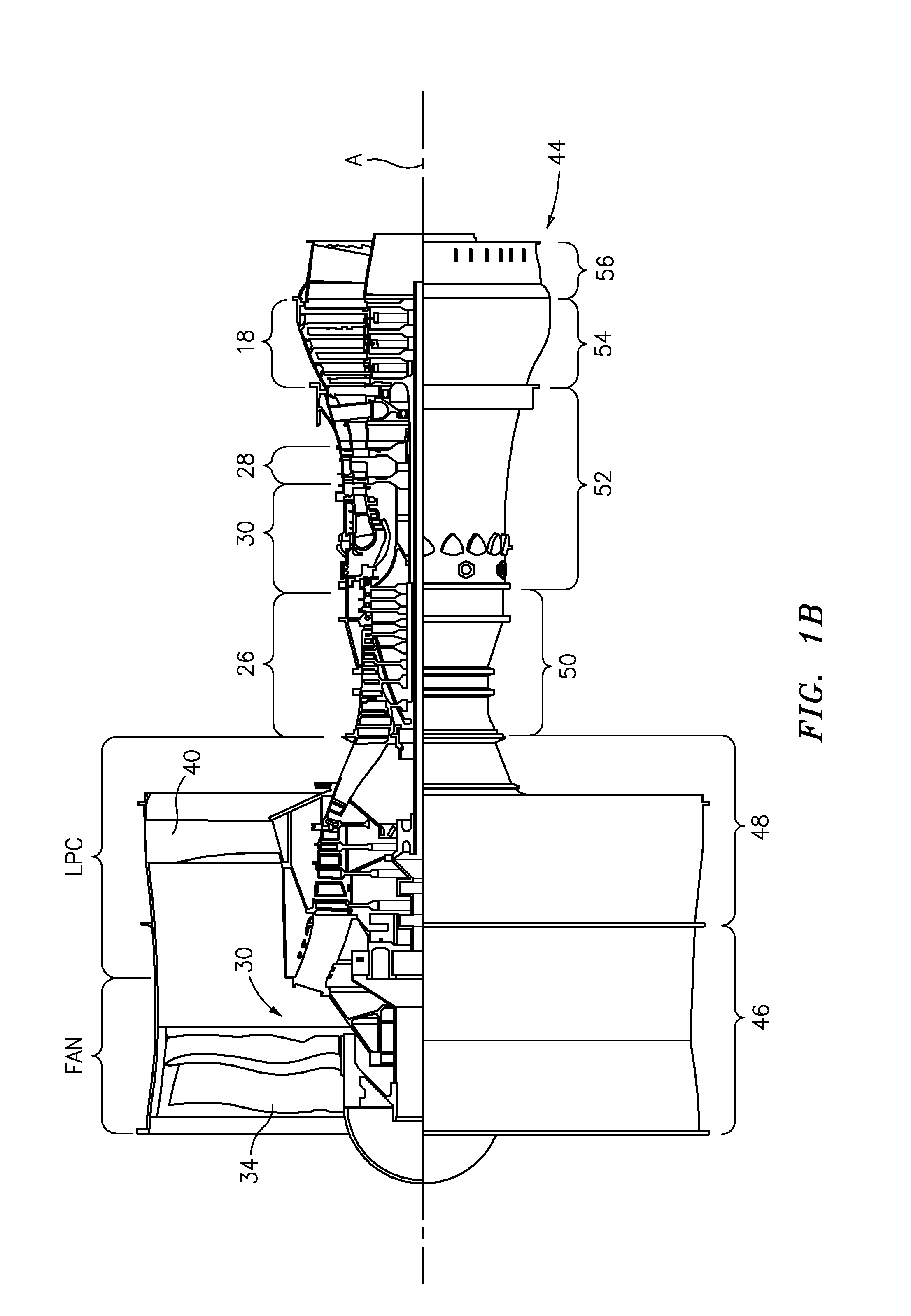
[0014]The engine 10 includes a core engine within a core nacelle C that houses a low pressure spool 14 and high pressure spool 24. The low pressure spool 14 generally includes a low pressure compressor 16 and low pressure turbine 18. The low pressure spool 14 drives a fan section 20 connected to the low pressure spool 14 either directly or through a gear train 25.

[0015]The high pressure spool 24 includes a high pressure compressor 26 and high pressure turbine 28. A combustor 30 is arranged between the high pressure compressor 26 and high pressure turbine 28. ...


PUM


Abstract

A thermal management system includes at least two of a multiple of heat exchangers arranged in an at least partial-series relationship.

Description

BACKGROUND OF THE INVENTION[0001]The present invention relates to Thermal Management Systems (TMS) with a shared heat exchanger flow.[0002]Thermal Management Systems (TMS) include heat exchangers and associated equipment which exchange gas turbine engine heat with an airflow or fuel flow. Gas turbine engine architecture typically dictates TMS heat exchanger placement.[0003]Conventional TMS heat exchanger locations may partially interrupt the engine thrust airflow and reduce engine efficiency. One conventional TMS heat exchanger placement is typically within a core cowl area and axially deep within a fan cowl. The heat exchanger airflow is ducted inward toward the engine centerline through the heat exchanger, then ducted outward to merge with the bypass flow. Such ducts may be relatively long and serpentine to guide the heat exchanger airflow away from, then back into the bypass flow. This location may also introduce mixing losses which may further detract from engine efficiency.[000...

Claims


Application Information

Patent Timeline
Patent Type & Authority Applications(United States)
IPC IPC(8): F02K3/02F02C7/12F02C7/18
CPCF02C7/14F02C7/185Y02T50/675F02K3/115Y02T50/671F02C7/224Y02T50/60
Inventor SUCIU, GABRIEL L.MERRY, BRIAN D.DYE, CHRISTOPHER M.
Owner RTX CORP
Why Eureka
Try Eureka