
Fin-type compound parabolic concentrator

Inactive Publication Date: 2009-07-30
THALES RES
View PDF4 Cites 16 Cited by
  • Summary
  • Abstract
  • Description
  • Claims
  • Application Information

AI Technical Summary

Benefits of technology

[0023]Accordingly, it is an object of the present invention to create the geometry that limits the angle of light striking a bi-facial photovoltaic cell when a flat bi-facial photovoltaic cell is employed as the fin in a fin-type compound parabolic concentrator.

Problems solved by technology

This means that photovoltaic wafer costs and any single step processing costs are approximately half of those for the plate type compound parabolic concentrators.
All conventional reflector-absorber configurations fall short of this theoretical limit, sometimes significantly.
In all cases, however, grazing rays tend to be reflected, and limiting θo is an essential design feature.
In addition to not providing guidance about how to construct a θi θo fin-type compound parabolic concentrator, the prior art does not provide any assurance that an ideal θo fin-type compound parabolic concentrator exists.

Method used


Image

  • Fin-type compound parabolic concentrator
  • Fin-type compound parabolic concentrator
  • Fin-type compound parabolic concentrator

Examples


Embodiment Construction

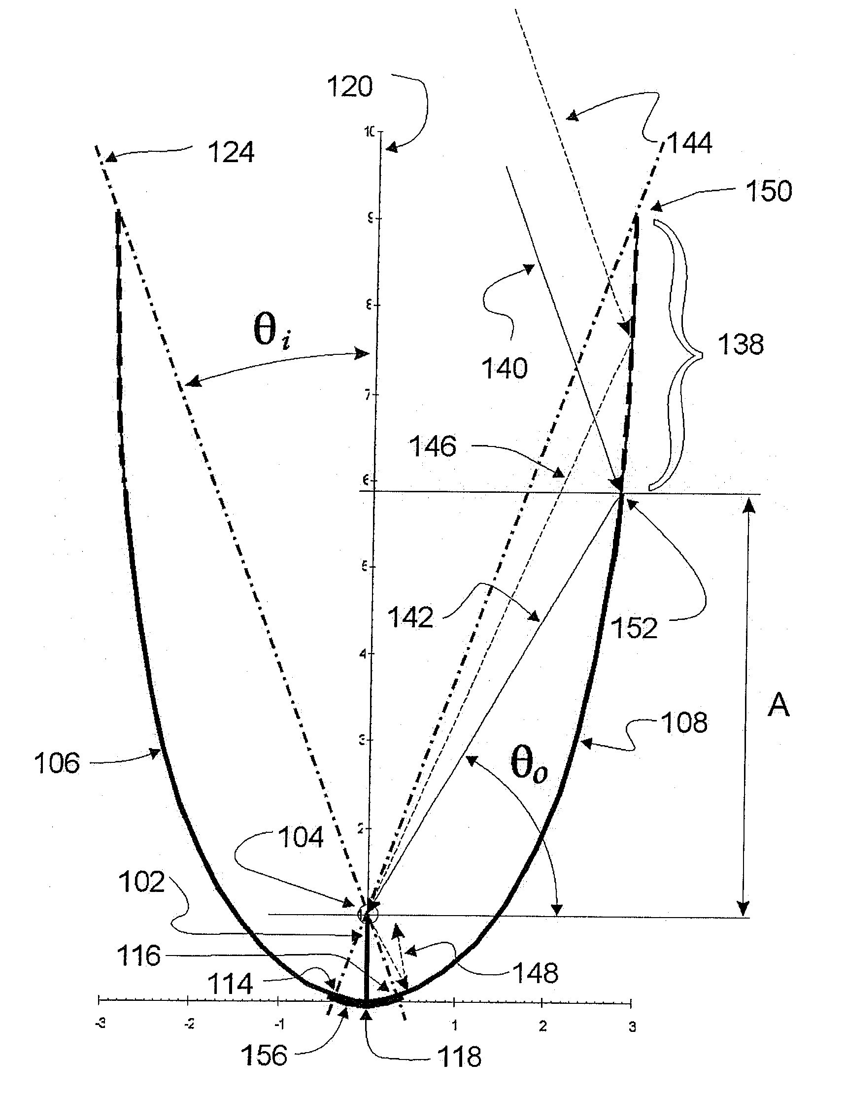
[0042]The invention relates to a fin-type compound parabolic concentrator which is designed to limit the light striking the photovoltaic cell absorber to an angle less than or equal to a critical angle θo. There are three components to the invention: truncating the semi-parabolic reflectors of the concentrator; configuring the limiting apex geometry of the bottom reflector of the concentrator; and connecting the apex geometry with the semi-parabolic reflectors.

[0043]Referring to FIG. 7, there is shown a fin-type compound parabolic concentrator 150 including a pair of opposed semi-parabolic reflectors 106, 108 arranged on opposite sides of a common plane 120 and having a focal point 104 on the common plane. The reflectors are rotated in opposite directions relative to the common plane through a rotational angle θi defined by lines extending from the apexes 114, 116 of each semi-parabolic reflector through the focal point 104. The concentrator further includes a generally arcuate bott...


PUM


Abstract

A fin-type compound parabolic concentrator includes a pair of semi-parabolic reflectors arranged on opposite sides of a common plane, the reflectors having a common focal point on the plane and being rotated through an angle defined by a line extending from the apex of each reflector through the focal point. A generally arcuate bottom reflector having a center line within the common plane is connected with the semi-parabolic reflectors. A bi-facial photovoltaic absorber is arranged in the common plane and extends from the focal point to the bottom reflector for absorbing rays of sunlight directed thereon from the reflectors. The absorber has a critical angle below which rays directed thereon will be substantially absorbed and above which rays directed thereon will be substantially reflected and the bottom reflector is configured to limit the angle of rays that strike said absorber to less than said critical angle.

Description

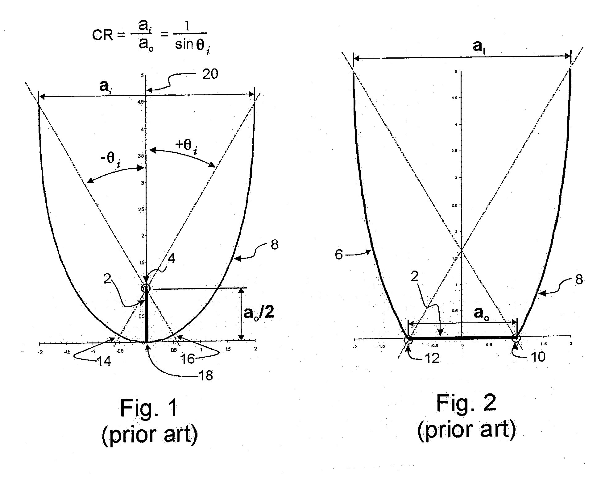
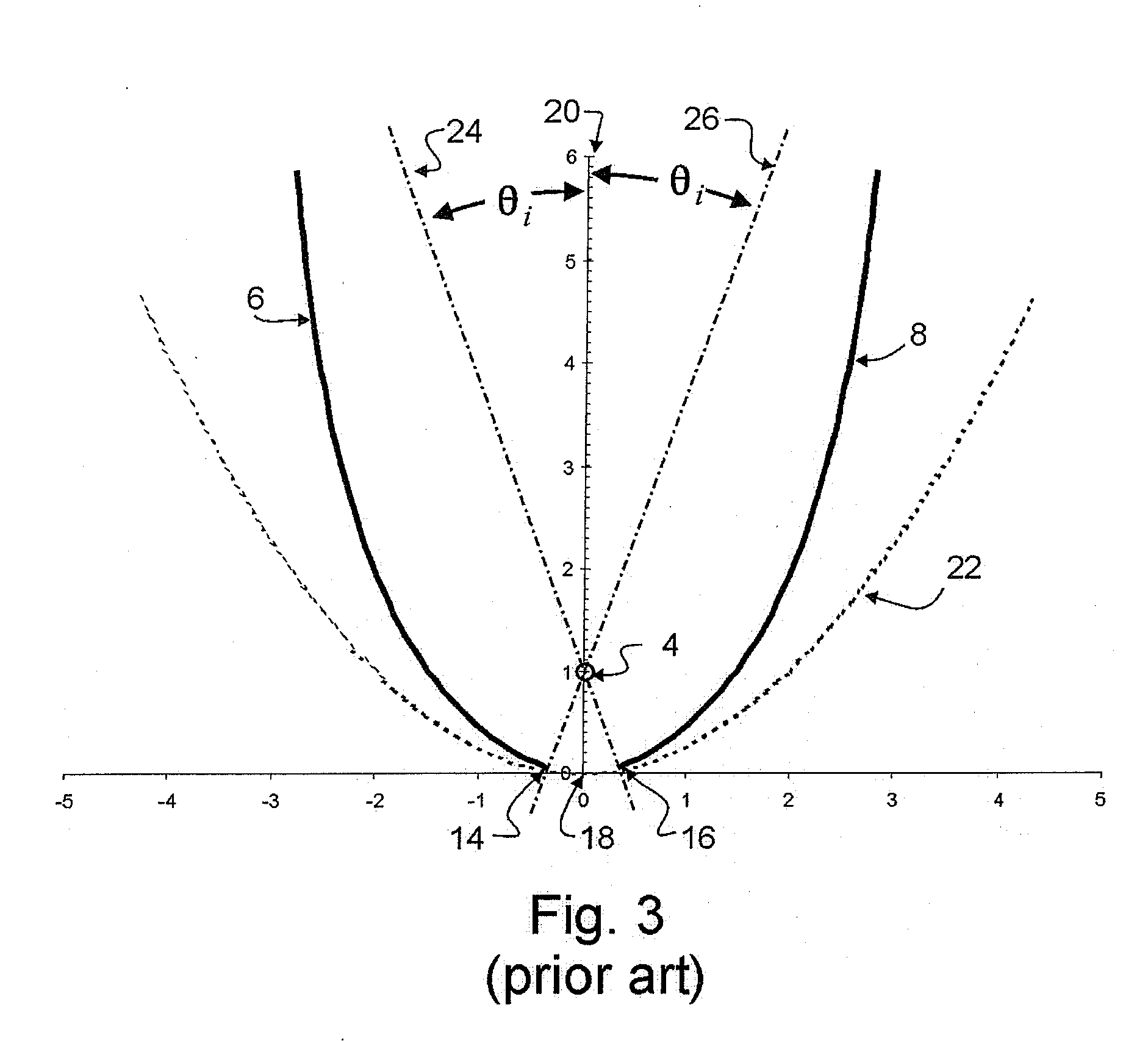
[0001]This application claims the benefit of U.S. provisional application No. 61 / 024,277 filed Jan. 29, 2008.BACKGROUND OF THE INVENTION[0002]The present invention relates to fin type compound parabolic concentrators (FT-CPCs) for use as static concentrators in cost effective solar photovoltaic (PV) systems. More specifically, the invention includes geometries that limit the angle of reflected rays striking the PV cell. This is called a θi θo FT-CPC or a θo FT-CPC where θi is the angle of rotation of the semi-parabolic reflectors of the concentrator and θo is the critical angle of the PV cell.BRIEF DESCRIPTION OF THE PRIOR ART[0003]A system based on FT-CPCs is disclosed in the L'Esperance U.S. Pat. No. 4,024,852 and a number of reflector shapes for such concentrators are disclosed in the Winston U.S. Pat. No. 4,002,499. These reflector shapes including a FT-CPC have since come to be known as ideal concentrators.[0004]There are two main types of compound parabolic concentrators using...

Claims


Application Information

Patent Timeline
IPC IPC(8): H01L31/00
CPCF24J2/1047F24J2/14H01L31/0547Y02E10/45Y02E10/52F24J2002/1042F24S23/80F24S23/74F24S2023/838Y02E10/40
Inventor PAVLAK, ALEXANDER J.
Owner THALES RES
Learn More