[0004]An object of the present invention is to provide a pneumatic tire having improved driving stability and wear resistance on dry road surfaces as well as an improved running performance on snow.
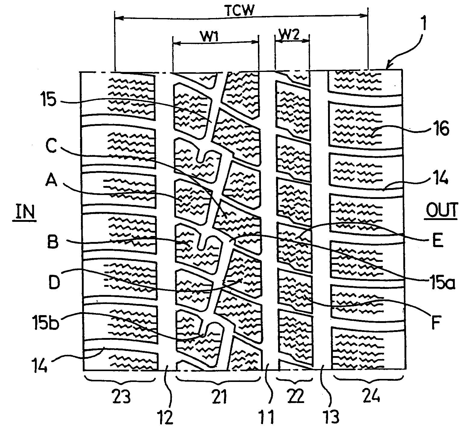
[0006]In the present invention, the tread portion is partitioned into the plurality of lines of land sections by the first, second, and third main grooves. The width of the first land section closer to the center of the vehicle is set greater than the width of the second land section farther from the center of the vehicle, and the inclined grooves each having a relatively large length are disposed in the first land section. This arrangement makes it possible to optimize the block rigidity, and to sufficiently secure the driving stability and wear resistance on dry road surfaces. Moreover, the inclined grooves disposed in the first land section make it possible to improve the running performance, such as driving stability and turnability, on snow.
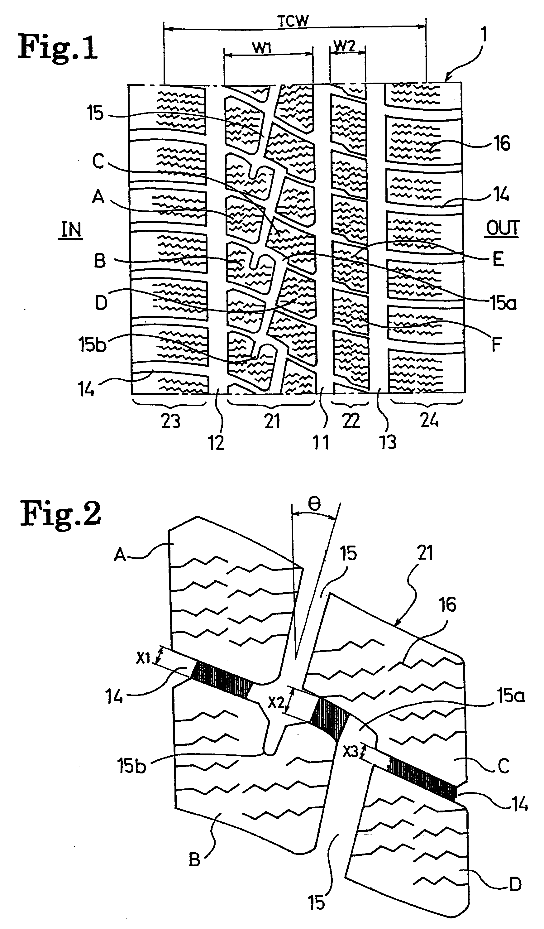
[0007]In the present invention, the following structure is preferably employed for achieving a good balance between the running performance on snow as well as the driving stability and wear resistance on dry road surfaces. Specifically, each inclined groove may communicate with three of the lug grooves, so that four types of blocks defined by the three lug grooves and the inclined groove are disposed as a repeating unit in the first land section. In addition, a plurality of blocks defined by the plurality of lug grooves may be disposed in the second land section. Moreover, a surface area Sa of a block A located in a region, closer to the center of the vehicle and closer to the other end of the inclined groove, of the first land section; a surface area Sb of a block B located in a region, closer to the center of the vehicle and closer to the one end of the inclined groove, of the first land section; a surface area Sc of a block C located in a region, farther from the center of the vehicle and closer to the other end of the inclined groove, of the first land section; a surface area Sd of a block D located in a region, farther from the center of the vehicle and closer to the one end of the inclined groove, of the first land section; a surface area Se of a block E, adjacent to the block C, in the second land section; and a surface area Sf of a block F, adjacent to the block D, in the second land section, may be set to satisfy the following relations. It goes without saying that the surface area mentioned here is the surface area of a ground-contacting surface.Sa=Se×92% to 100%,Sb=Sf×110% to 118%,Sc=Se×110% to 115%, andSd=Sf×95% to 100%.
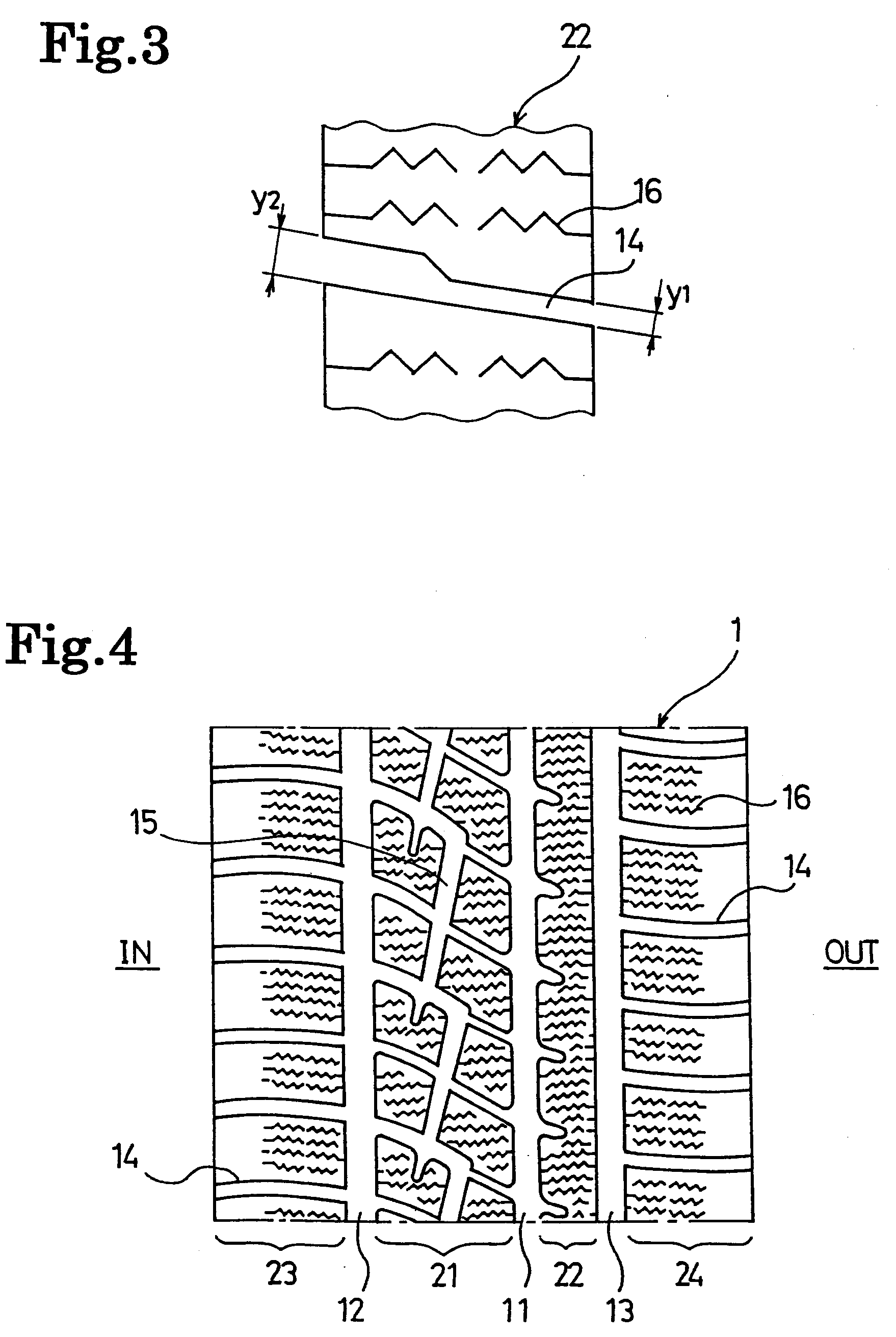
[0009]Further, it is also effective to employ the following structure for achieving a good balance between the running performance on snow as well as the driving stability and wear resistance on dry road surfaces. Specifically, the width of the first land section may be set at 50% to 70% of a tread contact half-width. The width of the second land section may be set at 15% to 35% of the tread contact half-width. A
groove width y1 of a part of each lug groove, farther from the center of the vehicle, in the second land section may be set to be 40% to 50% of a
groove width y2 of a part thereof, closer to the center of the vehicle, in the second land section. An inclination angle of the inclined grooves to the tire circumferential direction may be set at 10° to 30°. A sum of groove widths of the first, second, and third main grooves, may be set at 15% to 35% of a tread contact width.
[0011]In the present invention, when forming a pneumatic tire for use on icy and snowy roads represented by a studless tire, a plurality of sipes each extending in the tire width direction are preferably provided in each of land sections including the first and second land sections. The present invention provides significant operational effects when being applied to a pneumatic tire for use on icy and snowy roads; however, it is also possible to apply the present invention to an all-season pneumatic tire.
