Method and facility for disposing wet sludge

Active Publication Date: 2010-06-03
MITSUBISHI UBE CEMENT CORP
View PDF2 Cites 2 Cited by
  • Summary
  • Abstract
  • Description
  • Claims
  • Application Information

AI Technical Summary

Benefits of technology

[0026]Therefore, in particular, as in one of the third aspect and the eighth aspect, when the wet sludge disposal method and facility are applied to the disposal of wet sludge having a moisture content of 90% or less, significant effects can be obtained.
[0027]Further, according to the fifth aspect of the present invention, when water is fed to the annular gap part formed in the intermediate part in the thickness direction of the pipe by the water feed pump, the water is fed over the entire periphery of the inner wall surface of the pipe from the gap part through the nozzle part. Thereby, the entire periphery of the wet sludge can be effectively wetted by a smaller amount of water, which enables the wet sludge to be smoothly slid.
[0028]Further, according to the sixth aspect of the present invention, when the detection signal from the pressure detector indicates that the pressure in the pipe has reached th

Problems solved by technology

As for the disposal of wet sludge, such as sewage sludge, discharged from a sewage disposal plant, the conventional reclamation disposal and ocean disposal have become difficult because of the depletion of disposal site and the restrictions for preventing environmental pollution in recent years.
This results in a problem that the disposal method is inferior in cost effectiveness because additional costs, such as the cost for drying the wet sludge, and the cost for deodorizing exhaust gas generated during the drying treatment are required in addition to the cost originally required for the incineration.
As a result, in order to finally secure an extrusion pressure enough to charge the sewage sludge into the kiln inlet part, or the like,) at the distal end of the pipe, the pressure at the di

Method used


Image

  • Method and facility for disposing wet sludge
  • Method and facility for disposing wet sludge
  • Method and facility for disposing wet sludge

Examples


Example

[0033]1 Dry process kiln[0034]2 Kiln inlet part[0035]3 Preheater[0036]4 Calcining furnace[0037]5 Sludge tank[0038]6 Pressure feed pump[0039]7 Pipe[0040]8 Water injection apparatus[0041]12a, 12b Expanded diameter pipe[0042]14 Water injector[0043]15 Water feed pump[0044]16 Water feed line[0045]17 Pressure detector[0046]21 Gap part[0047]22 Nozzle part[0048]22a Distal end of nozzle part

BEST MODE FOR CARRYING OUT THE INVENTION

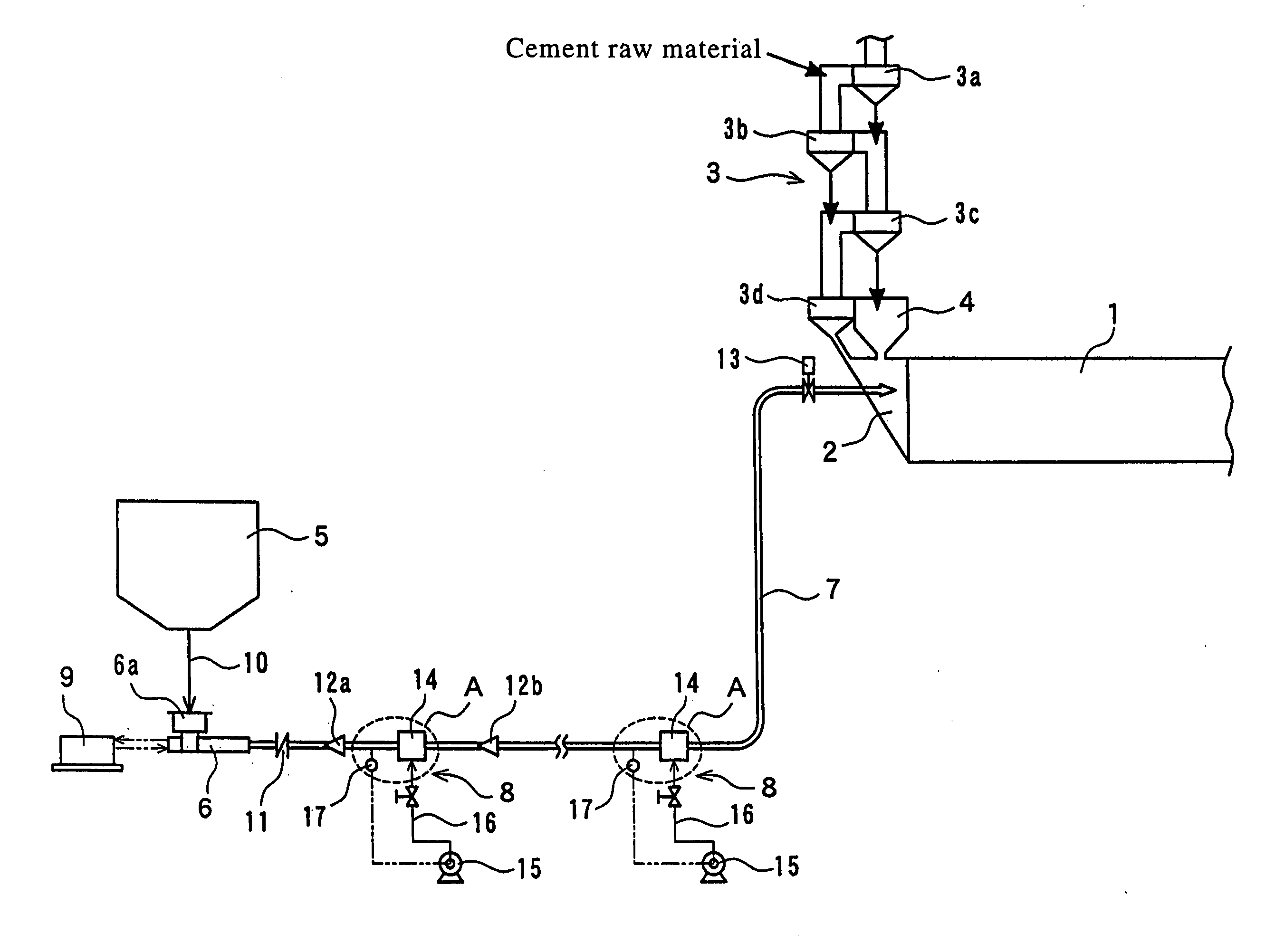
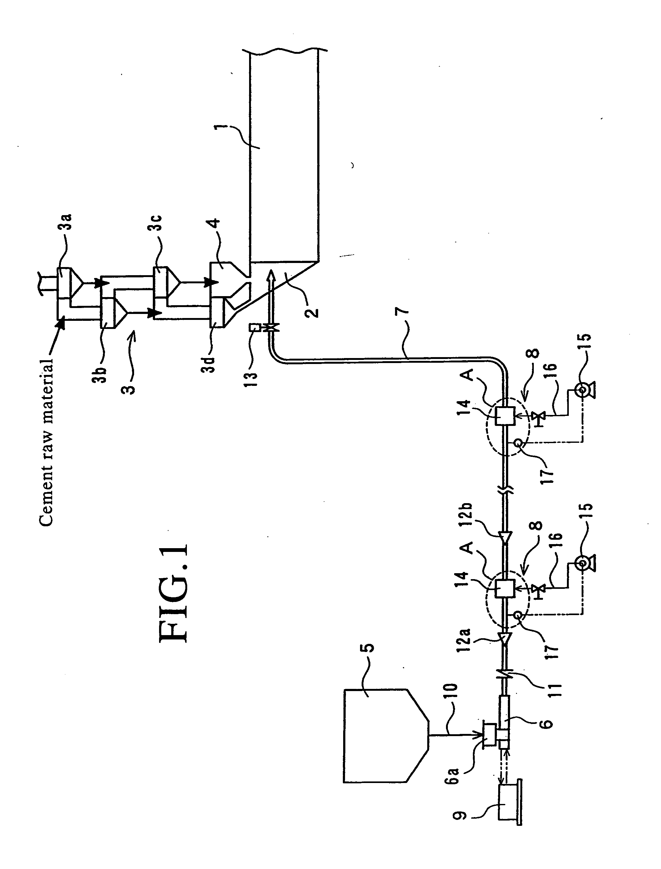
[0049]FIG. 1 to FIG. 3 show a best embodiment in which a wet sludge disposal facility according to the present invention is applied to a sewage sludge disposal facility installed in combination with a cement clinker manufacturing facility. Reference numeral 1 in FIG. 1 denotes a dry process kiln for calcining a cement raw material in the cement manufacturing facility.

[0050]The dry process kiln 1 is a rotary kiln which is rotatably provided around a shaft center. A preheater 3 for preheating the cement raw material is provided in a kiln inlet part 2 on the left side ...


PUM

PropertyMeasurementUnit
Fractionaaaaaaaaaa
Thicknessaaaaaaaaaa
Pressureaaaaaaaaaa

Abstract

An object of the present invention is to provide a wet sludge disposal method and facility capable of smoothly transferring wet sludge to a kiln inlet part, or the like, of a dry process kiln, by a low feeding pressure and without substantially increasing the moisture content in the wet sludge. To this end, the present invention is characterized, in a cement clinker manufacturing facility having a preheater (3) for preheating a cement raw material, and a dry process kiln (1) connected to the preheater (3) at the kiln inlet part (2) of the dry process kiln (1) and configured to calcine the preheated cement raw material, in that when wet sludge stored in a sludge tank (5) is transferred through a pipe by a pressure feed pump (6) and is directly charged into the kiln inlet part (2) to thereby be incinerated, the wet sludge is transferred to the side of the kiln inlet part (2) by such a way that water is intermittently or continuously fed between the wet sludge and the inner wall surface of the pipe (7) by a water injection apparatus (8) in at least one place of the pipe (7) between the pressure feed pump (6) and the kiln inlet part (2).

Description

TECHNICAL FIELD[0001]The present invention relates to a wet sludge disposal method and facility for efficiently performing final disposal of wet sludge, such as sewage sludge, in a cement clinker manufacturing facility.BACKGROUND ART[0002]As for the disposal of wet sludge, such as sewage sludge, discharged from a sewage disposal plant, the conventional reclamation disposal and ocean disposal have become difficult because of the depletion of disposal site and the restrictions for preventing environmental pollution in recent years. For this reason, there has been also proposed a method for incinerating the wet sludge in an incinerator. However, for example, even the sewage sludge which is formed into as dehydrated cake in the sewage disposal plant contains about 80% moisture.[0003]Therefore, in the disposal method using the incinerator, it is necessary to dry the wet sludge beforehand in order to reduce the thermal load of the incinerator. This results in a problem that the disposal m...

Claims


Application Information

Patent Timeline
IPC IPC(8): C04B7/48F23G7/04
CPCC02F11/008C04B7/24C04B7/43F27B7/32F27B7/20F27B7/2033C04B33/1321Y02W10/40Y02P40/10Y02P40/60
Inventor NAGAMIZU, KOJIKOGA, AKIHISATERUNUMA, HIROYUKINAKAI, YUSUKEHORIIKE, KOYURUITO, MASAFUMI
Owner MITSUBISHI UBE CEMENT CORP
Why Eureka
Try Eureka