

Cooling structure for bearing device
- Summary
- Abstract
- Description
- Claims
- Application Information
AI Technical Summary
Benefits of technology
Problems solved by technology
Method used
Image

Examples
first embodiment
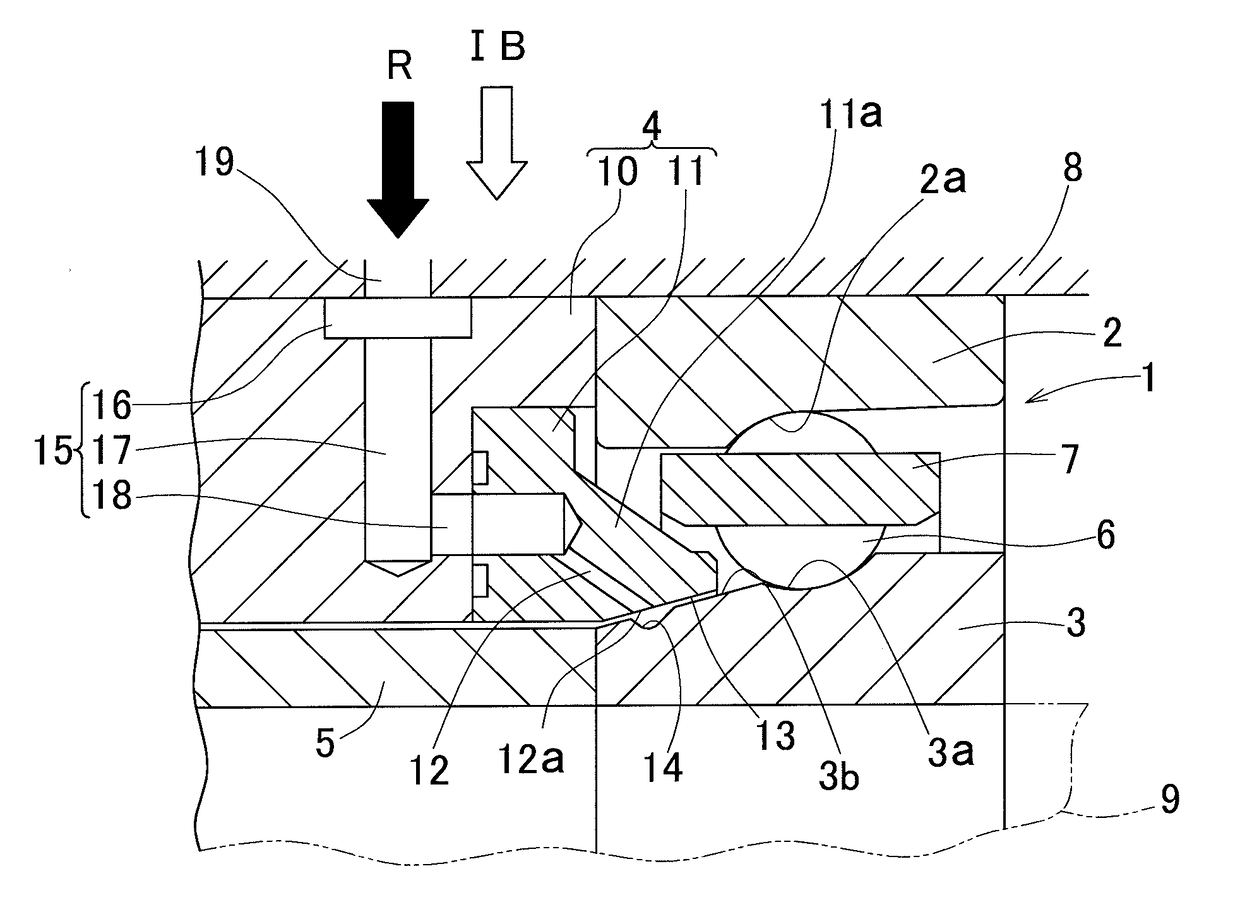
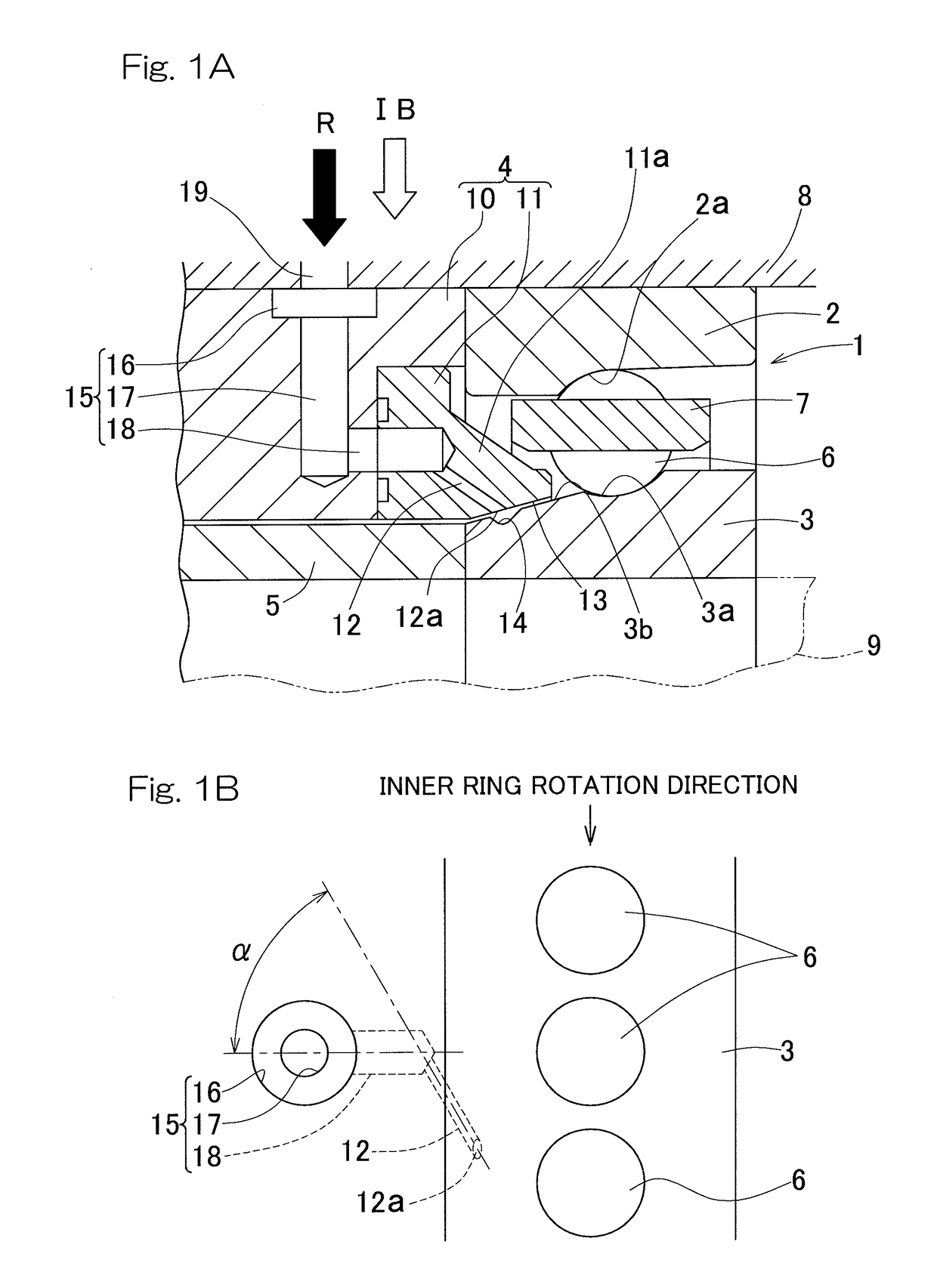
[0038]FIGS. 1A and 1B show the present invention. The cooling structure for a bearing device, includes a rolling bearing 1 having ring 2 and an inner ring 3, an outer ring spacer 4 disposed adjacent to the outer ring 2 and an inner ring spacer 5 are disposed adjacent to the inner ring 3. The rolling bearing 1 is, for example, an angular ball bearing, and a plurality of rolling elements 6 are interposed between a raceway 3a of the inner ring 3 and a raceway 2a of the outer ring 2. The rolling elements 6 are retained equidistantly in the circumferential direction by a retainer 7. The outer ring 2 and the outer ring spacer 4 are installed by being loosely fitted to a housing 8. The inner ring 3 and the inner ring spacer 5 are tightly fitted to a rotary shaft 9. A portion of the outer circumferential surface of the inner ring 3 that extends from the raceway 3a to the end face on the inner ring spacer 5 side is formed as an inclined surface 3b whose outer diameter is decreased toward the...
second embodiment
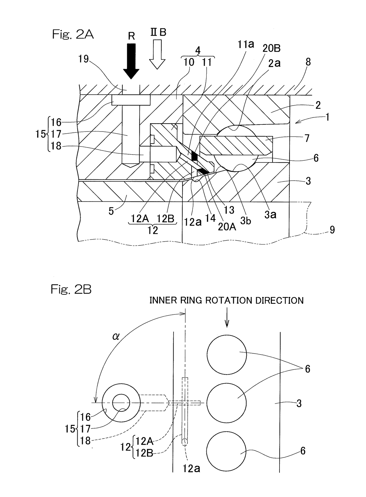
[0048]FIGS. 2A and 2B show the present invention. In this cooling structure for a bearing device, the inclination angle α of the central axis of the injection port 12a of each nozzle 12 is set to be parallel to the inner ring rotation direction, i.e., α=90°. The nozzle 12 includes: a first nozzle hole portion 12A extending obliquely to the inner diameter side from the leading end of the corresponding axial hole 18 of the introduction path 15, perpendicularly to the inner ring rotation direction as viewed in the radial direction; and a second nozzle hole portion 12B extending to the inner diameter side from the leading end of the nozzle hole 12A, parallel to the rotation direction of the inner ring 3. The nozzle hole portions 12A and 12B are both formed as through holes, and thereafter, portions of the through holes that require closing are closed by plug members 20A and 20B.
[0049]By forming each nozzle 12 in this manner, the inclination angle α of the central axis of the injection p...
PUM
| Property | Measurement | Unit |
|---|---|---|
| Angle | aaaaa | aaaaa |
| Angle | aaaaa | aaaaa |
| Diameter | aaaaa | aaaaa |
Abstract
Description
Claims
Application Information