Method of and a device for producing parts

a technology for producing parts and devices, applied in the direction of manufacturing tools, auxillary welding devices, soldering devices, etc., can solve the problems of inconvenient and expensiv

Inactive Publication Date: 2009-07-30
COOPER ALEX +2
View PDF2 Cites 7 Cited by
  • Summary
  • Abstract
  • Description
  • Claims
  • Application Information

AI Technical Summary

Benefits of technology

[0006]When the method is performed and the apparatus is designed in accordance with the present invention, it is not necessary to have a support of a great diameter, since the wire is held only at one location at which successive portions of wire are wound near one another, and connected with one another.

Problems solved by technology

Therefore, if it is necessary to produce a part of a great diameter, it is necessary to have a support of a great diameter, which is inconvenient, expensive, and in many instances unacceptable because of space limitations.

Method used


Image

  • Method of and a device for producing parts
  • Method of and a device for producing parts
  • Method of and a device for producing parts

Examples


Embodiment Construction

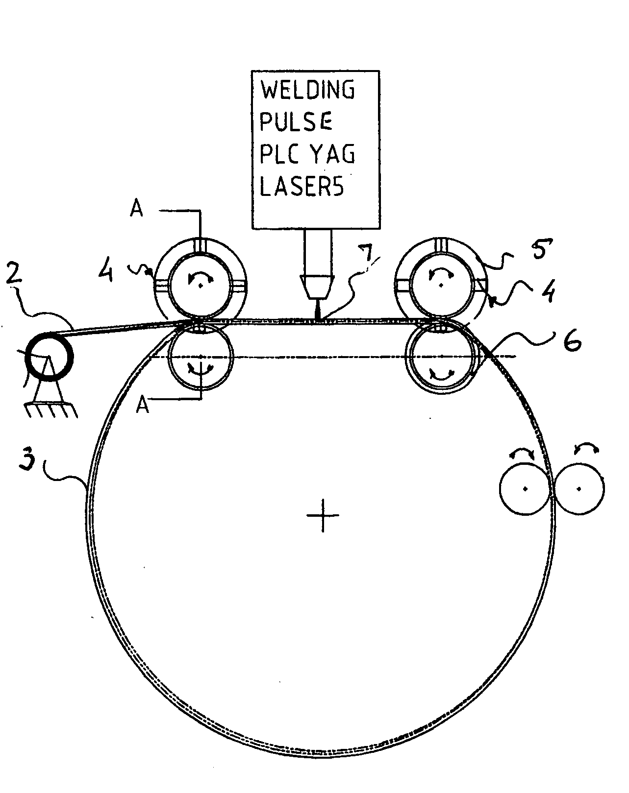
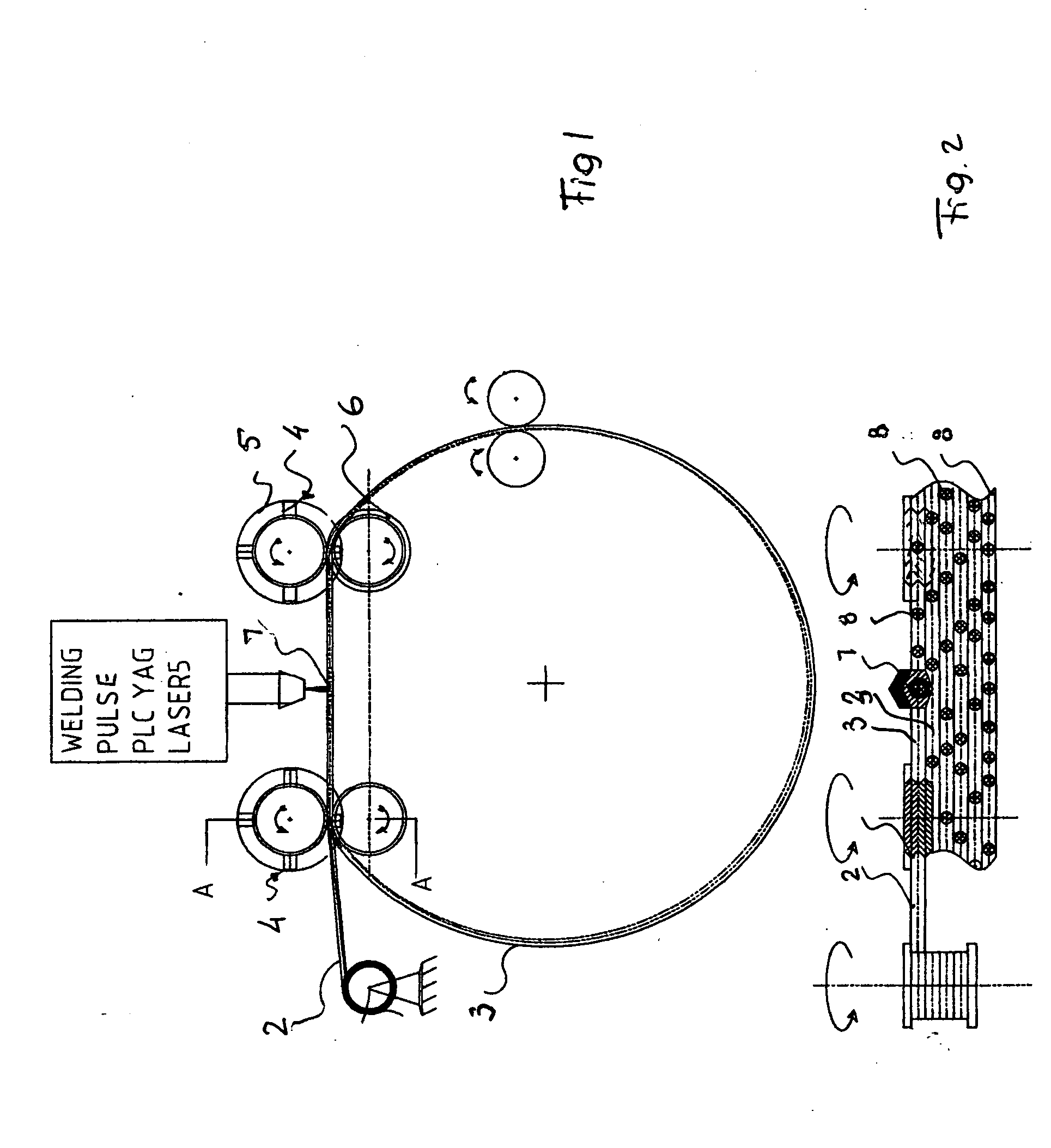
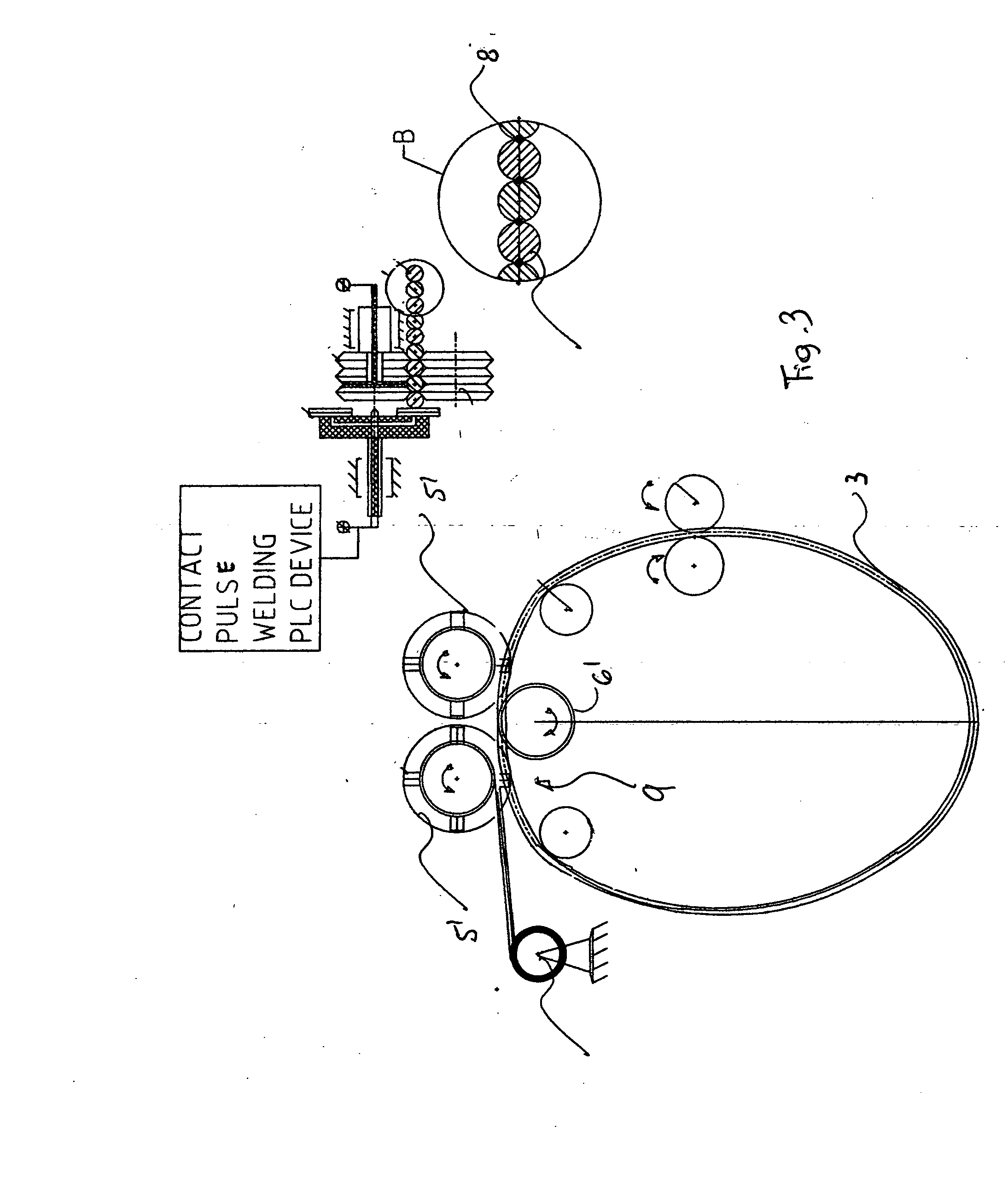
[0016]In accordance with the present invention a part which is identified as a whole with reference numeral 1 is produced from a wire, which is identified with reference numeral 2 and has a plurality of portions 3 that are formed during winding of the wire 2.

[0017]In an apparatus shown in FIG. 1 roller means are provided which are identified as a whole with reference numeral 4 and include upper rollers 5 and a lower rollers 6. The wire 2 is introduced between the rollers 5 and 6, and the rollers are driven in rotation by known means. During rotation of the rollers 5 and 6 the wire is wound forming a loop of a great diameter and so that subsequent portions of wire are arranged side-by-side with one another, preferably so as to be laterally in contact with one another.

[0018]The portions 3 of the wire 2 are then connected with one another by connecting means identified with reference numeral 7. The connecting means 7 can be of any type, for example welding means, glueing means, staplin...


PUM

PropertyMeasurementUnit
strengthaaaaaaaaaa
diameteraaaaaaaaaa
lengthaaaaaaaaaa

Abstract

For producing a part, a wire is wound so that portions of the wire extend along one another, and the portions of the wire are connected with one another, while during the winding the wire is supported so that the wire is not wound onto a support which fills it completely.

Description

BACKGROUND OF THE INVENTION[0001]The present invention relates to a method of and a device for producing parts, in particular with the use of a wire.[0002]It is known to produce a part by winding a wire on a support, such as for example a cylindrical support, so that convolutions or portions of the wire are wound around the support near one another, subsequently are connected with one another, for example by sintering, and then removed from the support. As a result, the part has a very high strength since it is composed of a plurality of wires. However, in the known method and the device it is necessary to provide a support on which the wire has to be wound. Therefore, if it is necessary to produce a part of a great diameter, it is necessary to have a support of a great diameter, which is inconvenient, expensive, and in many instances unacceptable because of space limitations.SUMMARY OF THE INVENTION[0003]Accordingly, it is an object of the present invention to provide a method of a...

Claims


Application Information

Patent Timeline
Patent Type & Authority Applications(United States)
IPC IPC(8): B65H81/02B65H75/38
CPCB21F15/08B29C65/1658B21F45/00B23K26/0823B23K26/22B23K37/047B23K2201/04B23K2201/32B29C53/568B29C53/58B29C65/02B29C65/16B29C65/48B29C65/56B29C65/562B29C66/21B29C66/65B29C66/69B21F37/00B29C65/00B23K2101/04B23K2101/32
Inventor COOPER, ALEXBEDERAK, YEVGENYBEDERAK, ALEXANDER
Owner COOPER ALEX
Why Eureka
Try Eureka