Voltage regulator

a voltage regulator and voltage regulator technology, applied in the direction of power conversion systems, dc-dc conversion, instruments, etc., can solve the problems of unstable output current iout at the time of short-circuited output terminals, and achieve the effect of reducing the fluctuation of output curren

Inactive Publication Date: 2009-07-30
SEIKO INSTR INC
View PDF4 Cites 23 Cited by
  • Summary
  • Abstract
  • Description
  • Claims
  • Application Information

AI Technical Summary

Benefits of technology

[0011]The present invention has been made in view of the above-mentioned problem, and provides a voltage regulator capable of reducing fluctuation of an output current even when an output terminal thereof is short-circuited.

Problems solved by technology

As a result, the output current Iout at a time at which the output terminal is short-circuited is not made stable.
In this case, there is a risk that the output current Iout does not have a short-circuit current value but has an unexpected current value, whereby the output voltage Vout becomes 0 volts.

Method used


Image

  • Voltage regulator
  • Voltage regulator
  • Voltage regulator

Examples


Embodiment Construction

[0019]Hereinafter, with reference to the drawings, an embodiment of the present invention is described.

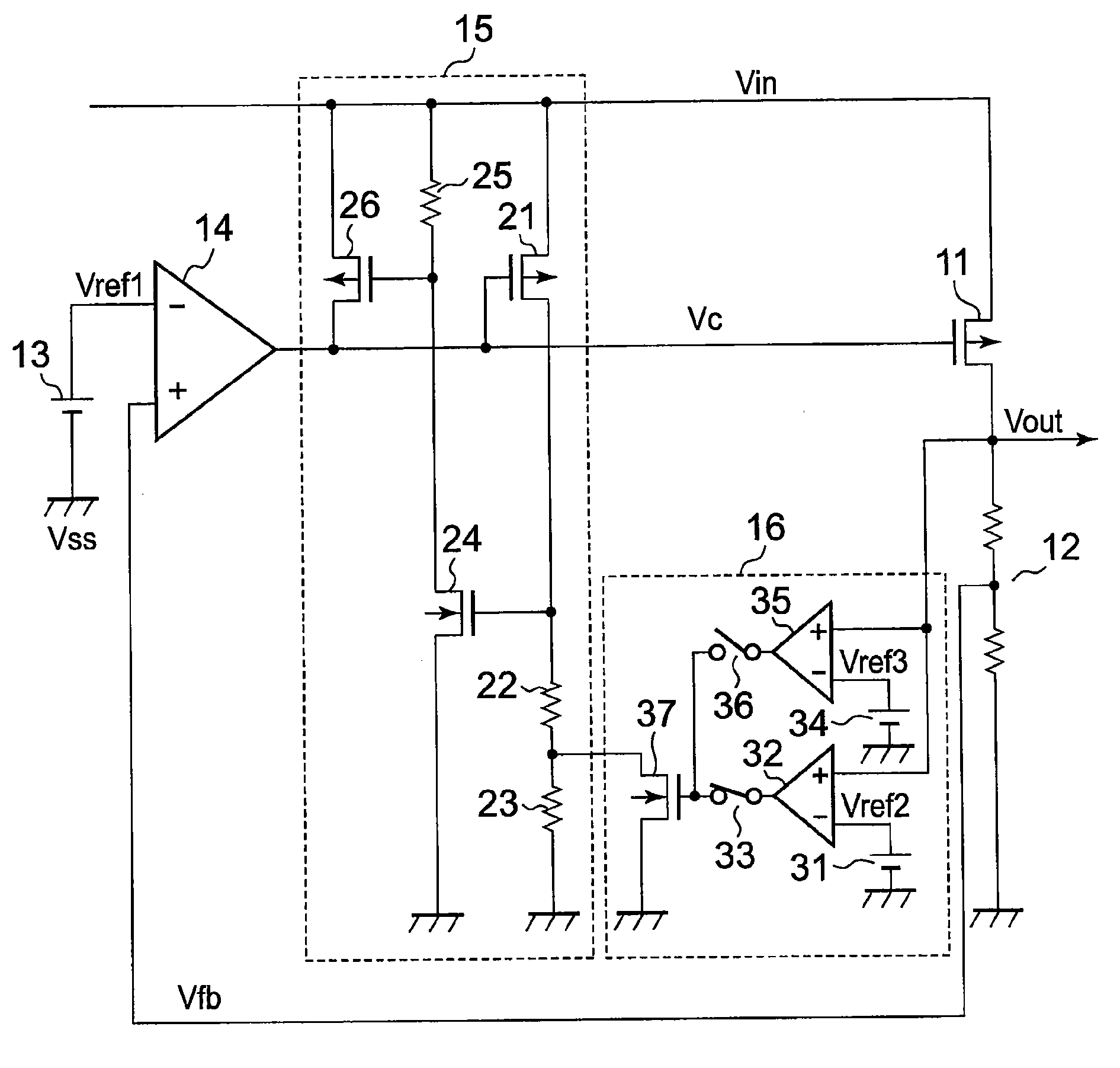
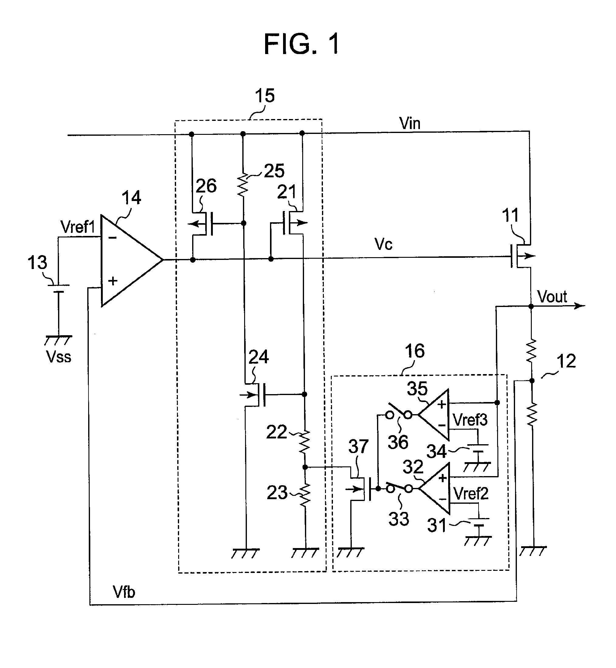
[0020]First, a structure of a voltage regulator is described. FIG. 1 is a diagram illustrating the voltage regulator.

[0021]The voltage regulator includes an output transistor 11, a voltage divider circuit 12, a reference voltage circuit 13, an amplifier circuit 14, an overcurrent protection circuit 15, and a voltage detection circuit 16. The overcurrent protection circuit 15 includes a PMOS transistor 21, resistors 22 and 23, an NMOS transistor 24, a resistor 25, and a PMOS transistor 26. The voltage detection circuit 16 includes a reference voltage circuit 31, a comparator 32, a switch 33, a reference voltage circuit 34, a comparator 35, a switch 36, and an NMOS transistor 37.

[0022]The output transistor 11 has a gate connected to an output terminal of the amplifier circuit 14, to a gate of the PMOS transistor 21, and to a drain of the PMOS transistor 26. The output transistor 11 h...


PUM


Abstract

Provided is a voltage regulator capable of reducing fluctuation of an output current even when an output terminal thereof is short-circuited. In a case where the output terminal of the voltage regulator is short-circuited, an output current (Iout) of the voltage regulator is limited and fixed to a limit current value. When an output voltage (Vout) of the voltage regulator decreases to have a value equal to or smaller than not a detection voltage value (Vref3) of a reference voltage circuit (34) but a detection voltage value (Vref2) of a reference voltage circuit (31), a second limit operation in which the output voltage (Iout) is further limited to be decreased is set. Further, in a case where the output terminal is short-circuited and then reset, when the output voltage (Vout) has a value equal to or larger than not the detection voltage value (Vref2) but the detection voltage value (Vref3), the second limit operation is canceled.

Description

RELATED APPLICATIONS[0001]This application claims priority under 35 U.S.C. § 119 to Japanese Patent Application No. JP2008-013477 filed on Jan. 24, 2008, the entire content of which is hereby incorporated by reference.BACKGROUND OF THE INVENTION[0002]1. Field of the Invention[0003]The present invention relates to a voltage regulator.[0004]2. Description of the Related Art[0005]First, a conventional voltage regulator is described. FIG. 3 is a diagram illustrating the conventional voltage regulator. FIG. 4 is a graph illustrating an output voltage with respect to an output current in the conventional voltage regulator.[0006]In FIG. 3, an output transistor 71 outputs an output voltage Vout based on an input voltage Vin and a control voltage Vc of an amplifier circuit 74. When the output voltage Vout of the voltage regulator decreases, the output voltage Vout is divided by a voltage divider circuit 72, whereby a divided voltage Vfb output by the voltage divider circuit 72 also decreases...

Claims


Application Information

Patent Timeline
Patent Type & Authority Applications(United States)
IPC IPC(8): G05F1/10
CPCG05F1/573G05F1/56H02M3/155
Inventor SUZUKI, TERUO
Owner SEIKO INSTR INC
Why Eureka
Try Eureka