Lens barrel and electron imaging device using the same

Inactive Publication Date: 2009-07-30
OLYMPUS CORP
View PDF1 Cites 3 Cited by
  • Summary
  • Abstract
  • Description
  • Claims
  • Application Information

AI Technical Summary

Benefits of technology

[0011]Therefore, in view of such circumstances, the object of the present invention is to provide with a lens barrel and an electronic imaging device using such a lens barrel, in which the size of the lens

Problems solved by technology

However, in a retracted position, each lens of the groups located around the retraction lenses in the imaging standby position usually approaches each other due to shortening of the lens barrel.
If the retracting space for the retraction lens group is configured to allow at least a part of a lens with largest aperture among those lenses located nearby the retraction lenses in the imaging standby position, to be present in the space in the radial direction, the size of the lens barrel in the radial direction will become

Method used


Image

  • Lens barrel and electron imaging device using the same
  • Lens barrel and electron imaging device using the same
  • Lens barrel and electron imaging device using the same

Examples


Embodiment Construction

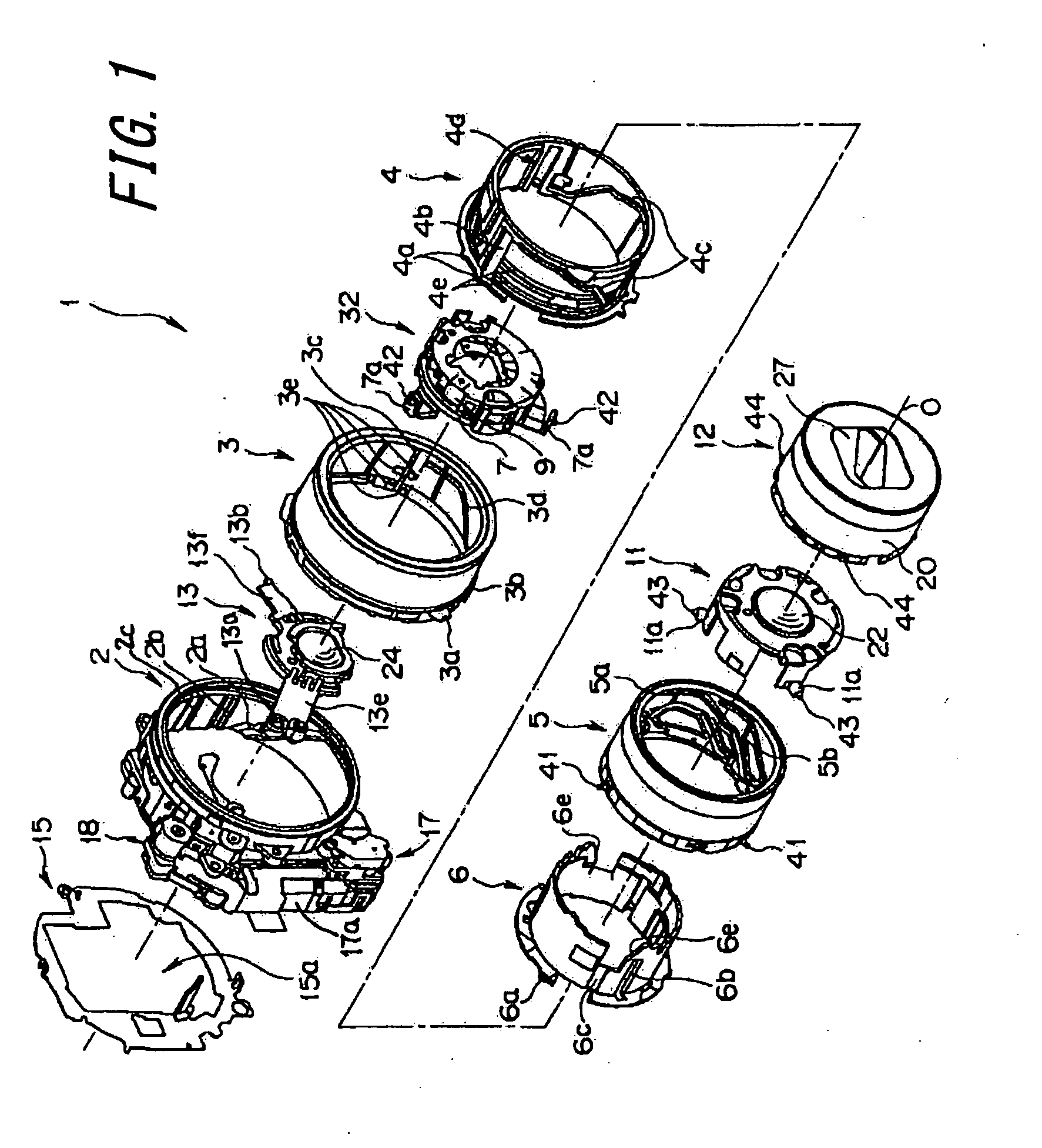
[0042]An embodiment of the present invention in case of applying to an electronic imaging device will now be described as an example, in reference to FIGS. 1-10.

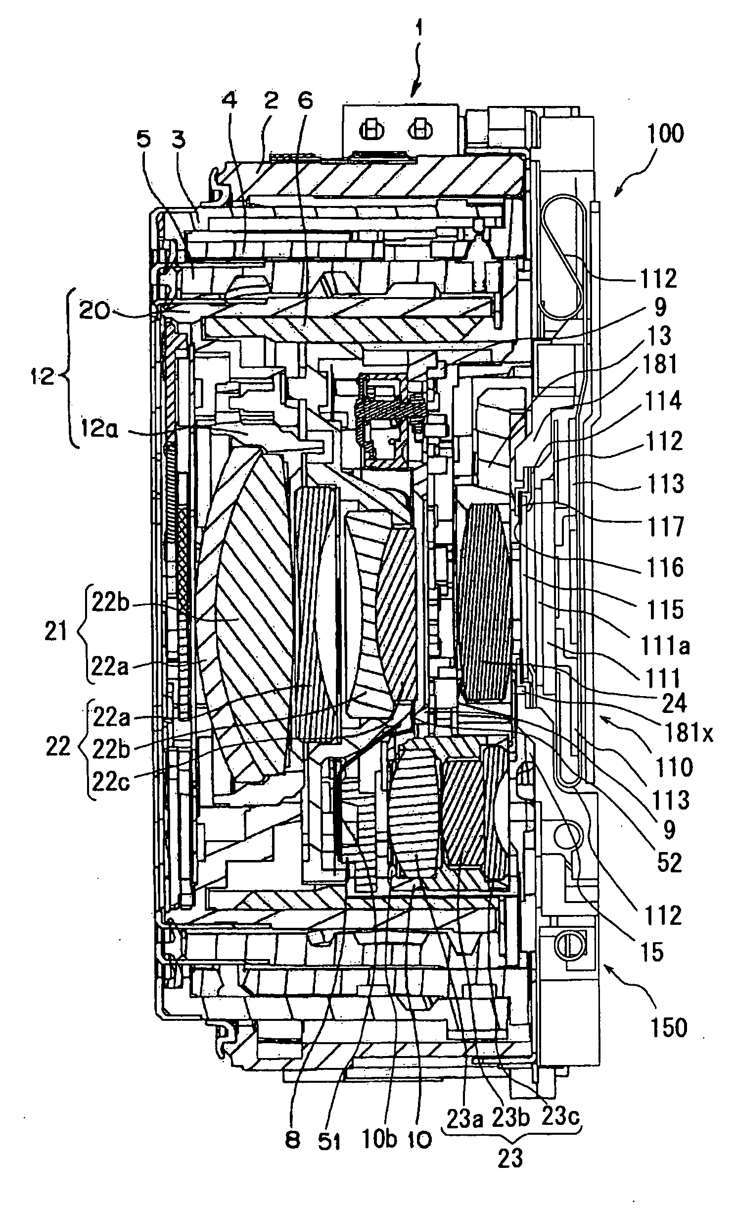
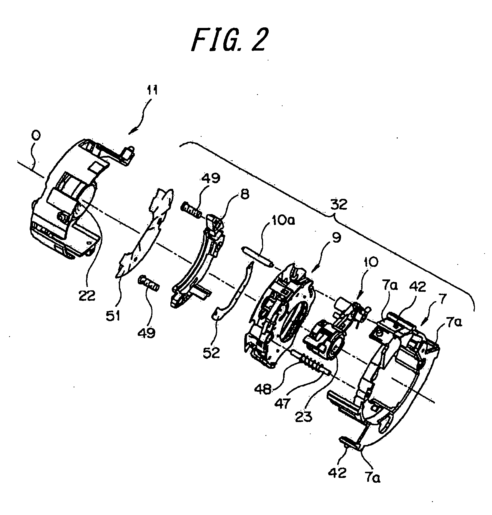
[0043]FIG. 1 is an exploded perspective view showing an arrangement of a lens barrel according to an embodiment of the present invention. FIG. 2 is an exploded perspective view of main part of a shutter / third group unit and a second group frame as shown in FIG. 1, being exploded. FIG. 3 is an enlarged perspective view of main parts of a shutter / third group unit as shown in FIG. 1, viewing from a front side thereof. FIG. 4 is an enlarged perspective view of main part of the shutter unit as shown in FIG. 3. FIGS. 5 and 6 are enlarged perspective views of main parts of the shutter / third group unit, in an imaging standby state and a retracted state, respectively, viewing from a rear side thereof. FIGS. 7 and 8 are cross sectional views along a plane including an optical axis of the lens barrel optical axis in the imaging standby...


PUM


Abstract

The inventive lens barrel comprises: a first group frame 12 retaining the first group lens 21 with a positive refractivity and being movable on the optical axis; a second group frame 11 retaining the second group lens 22 with a negative refractivity and being movable on the optical axis; a third group frame 10 retaining an aperture diaphragm 10b and the third group lens 23, and being movable on the optical axis and pivotable perpendicular to the optical axis in such a manner that the third group frame 10 can move the aperture diaphragm 10b and the third group lens 23 to the position on the optical axis O in a imaging standby state, in which the lens barrel 1 is extended, and move them to the position out of the optical axis O in the retracted state, in which the lens barrel 1 is shortened; and, a fourth group frame 13 retaining the fourth group frame 24 with a positive refractivity, and being movable on the optical axis, and being arranged such that it can retract the aperture diaphragm 10b and the third group lens 23 to a space between the object side end of the second group image side lens of the second group lens 22, which has a relatively smaller outer shape, and the image side end of the fourth group lens 24, in view from the direction perpendicular to the optical axis, under the retracted state.

Description

CROSS-REFERENCE TO APPLICATIONS[0001]The present application claims the priorities of Japanese Patent Application No. 2008-9604 filed on Jan. 18, 2008 and Japanese Patent Application No. 2008-311894 filed on Dec. 8, 2008, which are herein incorporated in their entirety for reference.FIELD OF THE INVENTION[0002]The present invention relates to a lens barrel and an electronic imaging device using the same.BACKGROUND OF THE INVENTION[0003]Conventionally, a lens barrel telescopically adjustable in its whole length in a direction of optical axis is in practical and widespread use. Such a lens barrel can be expanded and contracted between an imaging standby position, in which the lens barrel expands forward from its applied camera body, and a retracted position, in which the lens barrel is shortened than the imaging standby position and stored in the camera body.[0004]In such an extensible lens barrel, under the retracted position, part of lens group of an imaging optical system generally...

Claims


Application Information

Patent Timeline
IPC IPC(8): G02B9/34G02B7/10
CPCG02B7/021G02B7/026G02B7/023
Inventor SHIMAZAKI, YASUNARIKANETA, TAKAHIRO
Owner OLYMPUS CORP
Why Eureka
Try Eureka