
Illuminating device with light-emitting diode light

a technology of light-emitting diodes and illumination devices, which is applied in the direction of fixed installation, lighting and heating equipment, lighting support devices, etc., can solve the problems of visual deviation and relative small volume, and achieve the effect of eliminating the problem

Inactive Publication Date: 2009-07-30
LIN CHU HSIEN
View PDF11 Cites 20 Cited by
  • Summary
  • Abstract
  • Description
  • Claims
  • Application Information

AI Technical Summary

Benefits of technology

[0006]A primary object of the present invention is to provide an illuminating device with LED light source, which is able to convert a plurality of LED point light sources into a complete area light source, so as to provide more evenly projected lights and upgraded illuminating effect.
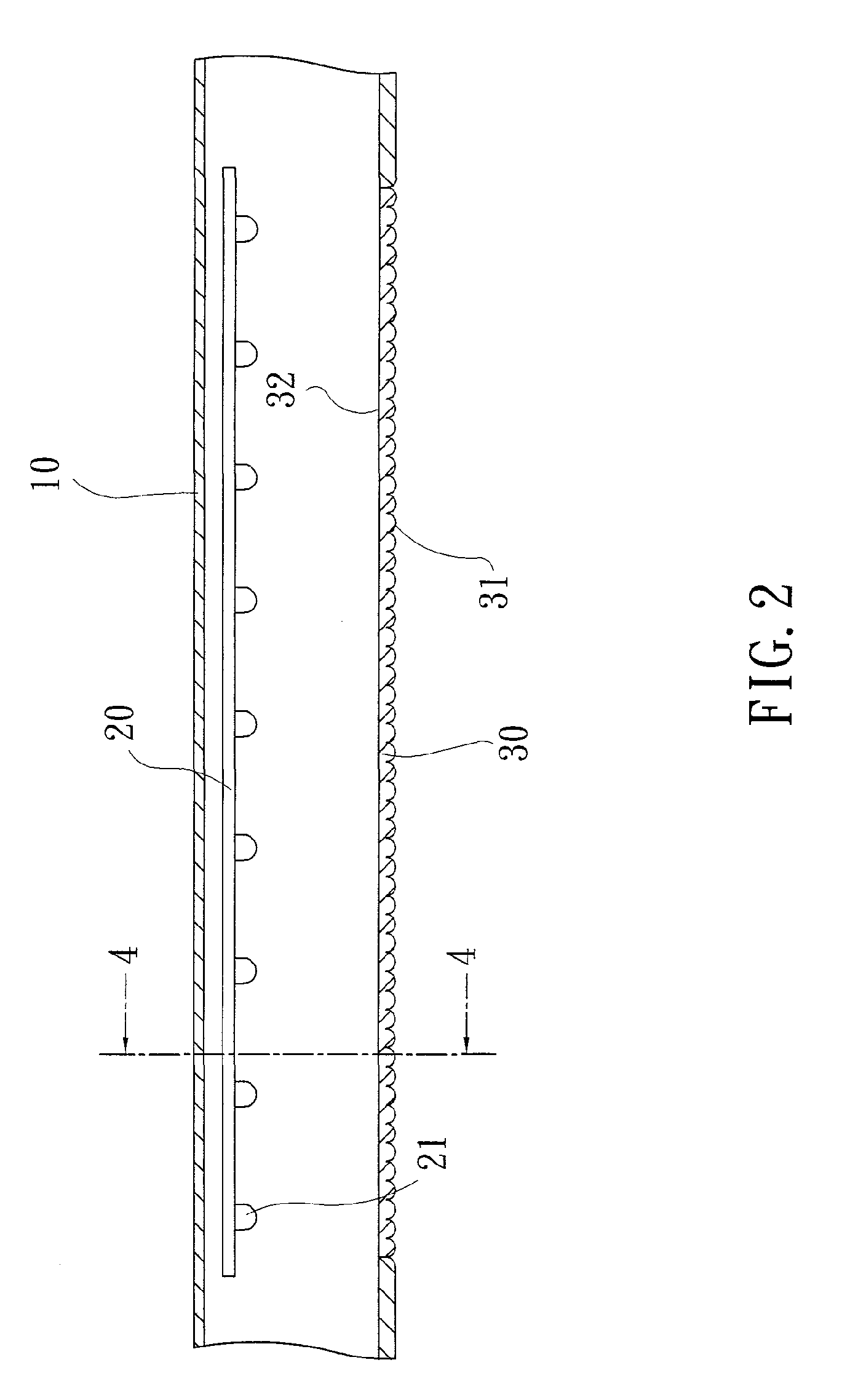
[0008]The elongated arch-sectioned transparent plate has a length and a width large enough for covering all the LED lamps. And, each of the curved ridges on the arch-sectioned transparent plate forms a convex lens to provide the light condensing effect.
[0010]The illuminating device with LED light source according to the present invention is advantageous because it converts a plurality of point light sources provided by the LED lamps into an area light source to eliminate the problem of overlapped images that are usually caused by multiple point light sources. Therefore, the LED illuminating device of the present invention can conveniently substitute for the conventional lighting devices.

Problems solved by technology

However, the LED has a relatively small volume to provide only a point light source.
When lights from two or more point light sources are projected on an object, there will be overlapped images to cause visual deviation.
It is therefore an important issue of how to effectively apply the LEDs to illuminating devices.

Method used


Image

  • Illuminating device with light-emitting diode light
  • Illuminating device with light-emitting diode light
  • Illuminating device with light-emitting diode light

Examples


Embodiment Construction

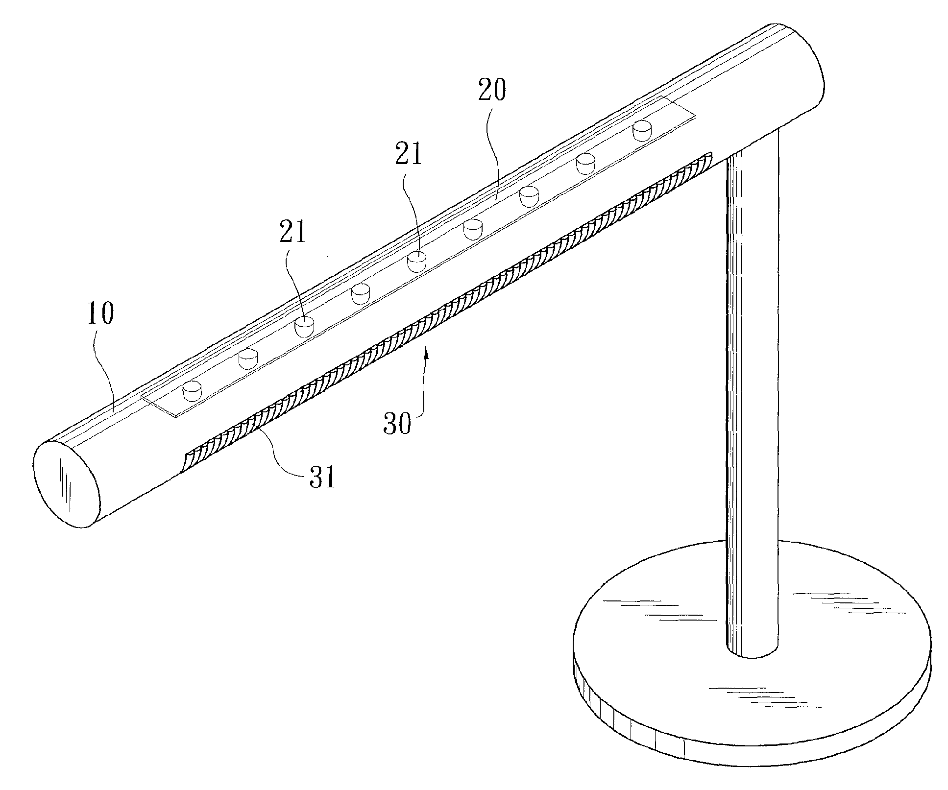
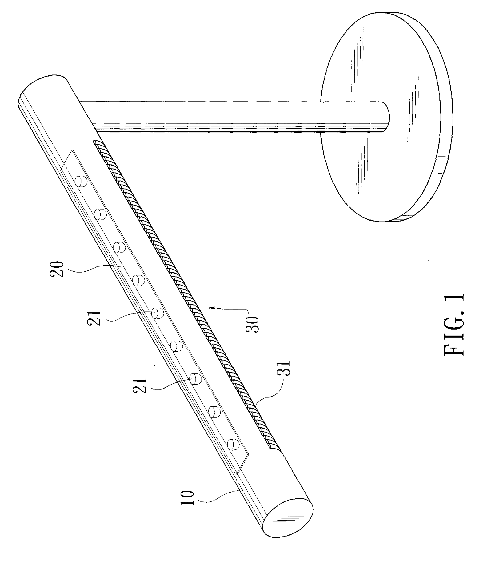
[0016]Please refer to FIGS. 1 to 4. An illuminating device with LED light source according to a preferred embodiment includes a circuit board 20, an elongate arch-sectioned transparent plate 30, and a lamp holder 10. The arch-sectioned transparent plate 30 is located below the circuit board 10, so that lights emitted from a plurality of LED lamps 21 mounted on the circuit board 20 must first pass through the plate 30 before being projected outward.

[0017]The LED lamps 21 can be arranged in line on the circuit board 20. The number of the LED lamps 21 is at least two. In the illustrated preferred embodiment, there are nine LED lamps 21. Since the illuminating device is used to illuminate downward, the LED lamps 21 are mounted to a lower face of the circuit board 20.

[0018]The arch-sectioned transparent plate 30 has a length and a width sufficient for covering all the LED lamps 21 on the circuit board 20. An outer surface of the plate 30 is formed with a plurality of curved ridges 31, wh...


PUM


Abstract

An illuminating device with LED light source includes a circuit board and an elongated arch-sectioned transparent plate. The circuit board has at least two LED lamps arranged in line. The transparent plate is located below the circuit board and is large enough to cover all the LED lamps. The arch-sectioned transparent plate is provided on an outer surface with a plurality of curved ridges, which are parallelly and closely arranged side by side. Lights emitted from the LED lamps and passed through the arch-sectioned transparent plate are condensed by the curved ridges. Therefore, the arch-sectioned transparent plate with the curved ridges forms an area light source. That is, point light sources provided by the LED lamps are converted into an elongated area light source by the curved ridges.

Description

FIELD OF THE INVENTION[0001]The present invention relates to an illuminating device with light-emitting diode (LED) light source, and more particularly to a device capable of converting LED point light sources into an elongated area light source, so that the device is suitable for use as an illuminating device.BACKGROUND OF THE INVENTION[0002]Most of the currently available illuminating devices are fluorescent tube lamps and incandescent bulbs. The tube lamps either have an elongated tube or a ring-shaped tube. And, the bulbs generally have a spherical shape or a coil shape formed from a thin tube.[0003]A light-emitting diode (LED) has the advantages of low power consumption, high lighting efficiency, small volume, etc. and has been widely used as an indicator lamp in electric circuits. The technique for producing LED is highly matured now, and the brightness of LED has reached the level high enough for using in illumination. Therefore, some lighting fixture manufacturers have tried...

Claims


Application Information

Patent Timeline
IPC IPC(8): F21V33/00F21V21/00
CPCF21S4/008F21S6/003F21S8/033F21S8/04F21Y2103/003F21V3/02F21V5/02F21Y2101/02F21S8/043F21S4/28F21Y2103/10F21Y2115/10
Inventor LIN, CHU-HSIEN
Owner LIN CHU HSIEN
Learn More