Method for transmitting and receiving channel state information periodically or aperiodically

a channel state and periodicity technology, applied in the field of periodic or aperiodical transmission and receiving channel state information, to achieve the effect of effective transmission and guaranteeing the capability of error detection of the base station

a channel state and periodicity technology, applied in the field of periodic or aperiodical transmission and receiving channel state information, to achieve the effect of effective transmission and guaranteeing the capability of error detection of the base station

US20090190528A1Active Publication Date: 2009-07-30LG ELECTRONICS INC

Image

  • Method for transmitting and receiving channel state information periodically or aperiodically
  • Method for transmitting and receiving channel state information periodically or aperiodically
  • Method for transmitting and receiving channel state information periodically or aperiodically

Examples


Embodiment Construction

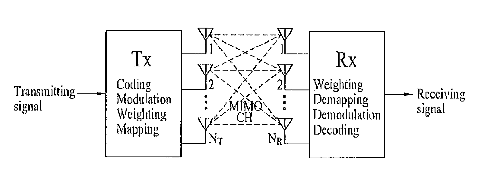
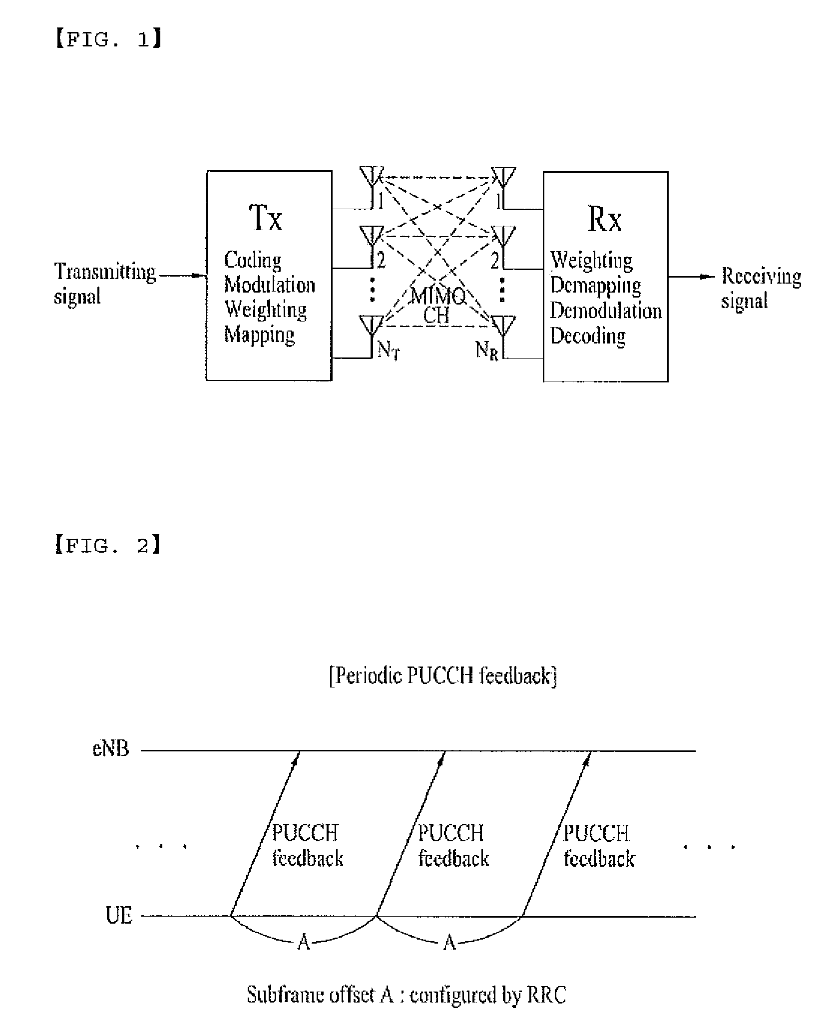
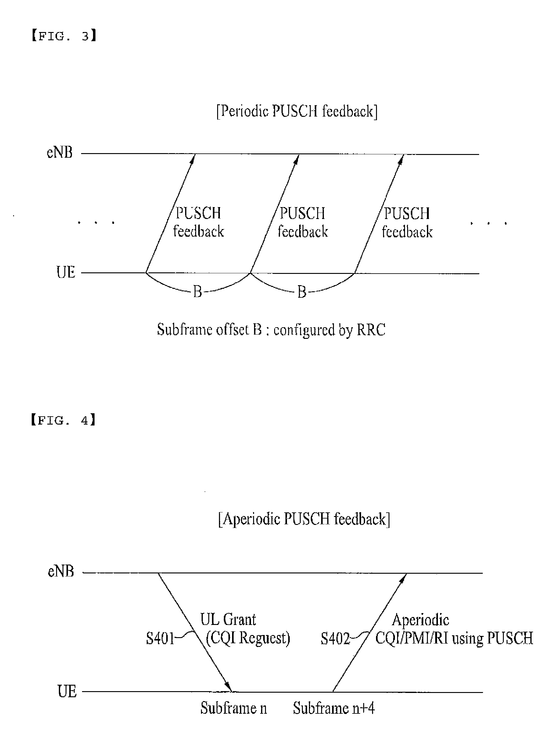
[0052]Reference will now be made in detail to the preferred embodiments of the present invention, examples of which are illustrated in the accompanying drawings. Wherever possible, the same reference numbers will be used throughout the drawings to refer to the same or like parts. The following embodiments of the present invention may be modified into various formats, and the scope of the present invention is not limited to only the following embodiments and can also be applied to other examples.

[0053]For the convenience of description and better understanding of the present invention, the following detailed description will disclose a variety of embodiments and modifications of the present invention. However, those skilled in the art will readily understand and implement the embodiments and modifications of the present invention. In some cases, in order to prevent ambiguous concepts of the present invention from occurring, conventional devices or apparatus well known to those skille...


PUM


Abstract

A method for transmitting and receiving channel state information (CSI) periodically and aperiodically is disclosed. The method for aperiodically transmitting channel state information (CSI) by a terminal includes receiving an indicator requesting a channel state information report of a downlink channel from a base station over a downlink control channel, and aperiodically transmitting the channel state information (CSI) to the base station over a physical uplink shared channel (PUSCH) upon receiving the indicator from the base station.

Description

CROSS-REFERENCE TO RELATED APPLICATIONS[0001]This application claims the benefit of the U.S. Provisional Patent Application No. 61 / 019,843, filed on Jan. 8, 2008, which is hereby incorporated by reference as if fully set forth herein.[0002]This application claims the benefit of the Korean Patent Application No. 10-2008-0135367, filed on Dec. 29, 2008, which is hereby incorporated by reference as if fully set forth herein.BACKGROUND OF THE INVENTION[0003]1. Field of the Invention[0004]The present invention relates to a method for enabling a terminal to periodically and / or aperiodically report channel state information to a base station, and a method for enabling the base station to receive the channel state information, wherein it is assumed that the channel state information for use in a multi-antenna system (i.e., a Multiple-Input Multiple-Output (MIMO) system) includes a channel quality indicator (CQI), a preceding matrix index (PMI), and a rank indicator (RI).[0005]2. Discussion ...

Claims


Application Information

Patent Timeline
30 Jul 2009
Publication
US20090190528A1
IPC
H04W4/00
CPC
H04B7/0417; H04B7/0639; H04B7/0632; H04B7/063
Inventors
CHUNG, JAE HOON; LEE, MOON II