Laser device

a laser and laser pulse technology, applied in the direction of laser details, optical resonator shape and construction, electrical apparatus, etc., can solve the problems of difficult to predict the delay period, the timing of the laser pulse emission cannot be precisely predicted, and the controllable modulator can be easily damaged, etc., to achieve high precision

Inactive Publication Date: 2009-07-30
INSTITUT FRANCO ALLEMAND DE RES & DEVS DE SAINT LOUIS
View PDF6 Cites 4 Cited by
  • Summary
  • Abstract
  • Description
  • Claims
  • Application Information

AI Technical Summary

Benefits of technology

[0013]One object is to design a laser device such that the generation time of...

Problems solved by technology

A disadvantage of the laser device of DE 41 02 409 C2 is that, despite the generation of a pulse, which is stable in time, the delay period is difficult to predict.
Therefore, the timing of the emission of the laser pulse cannot be precisely predicted, even if the beginning of pumping is known.
A further di...

Method used


Image

  • Laser device
  • Laser device
  • Laser device

Examples


Embodiment Construction

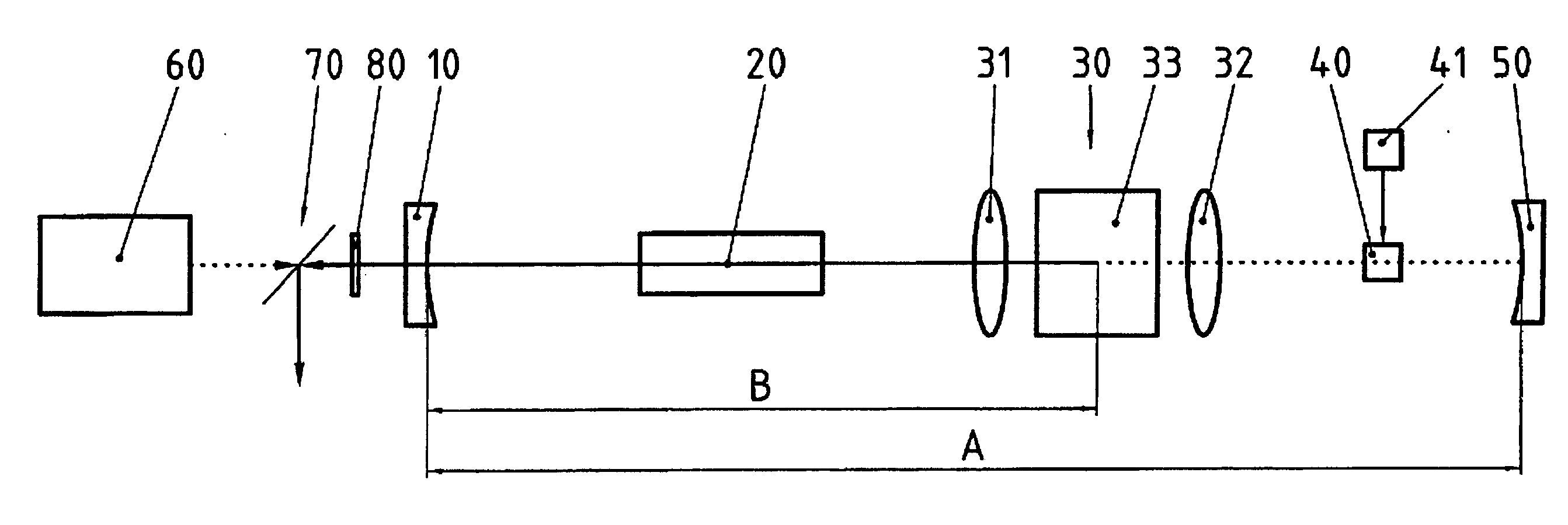
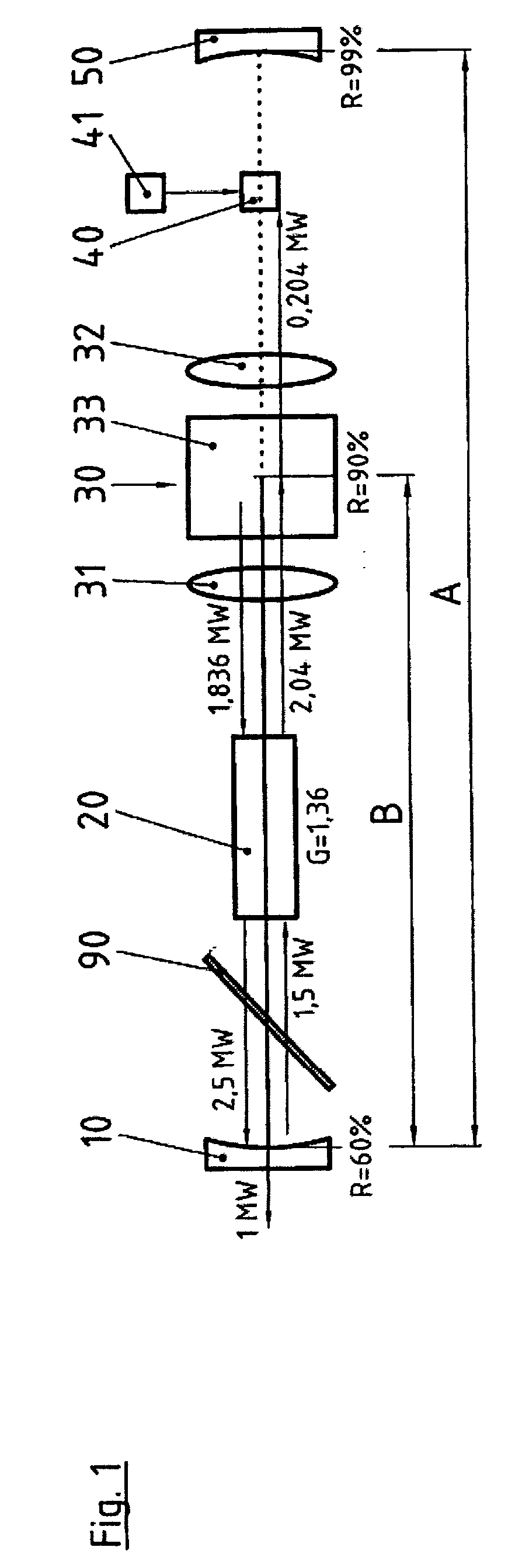
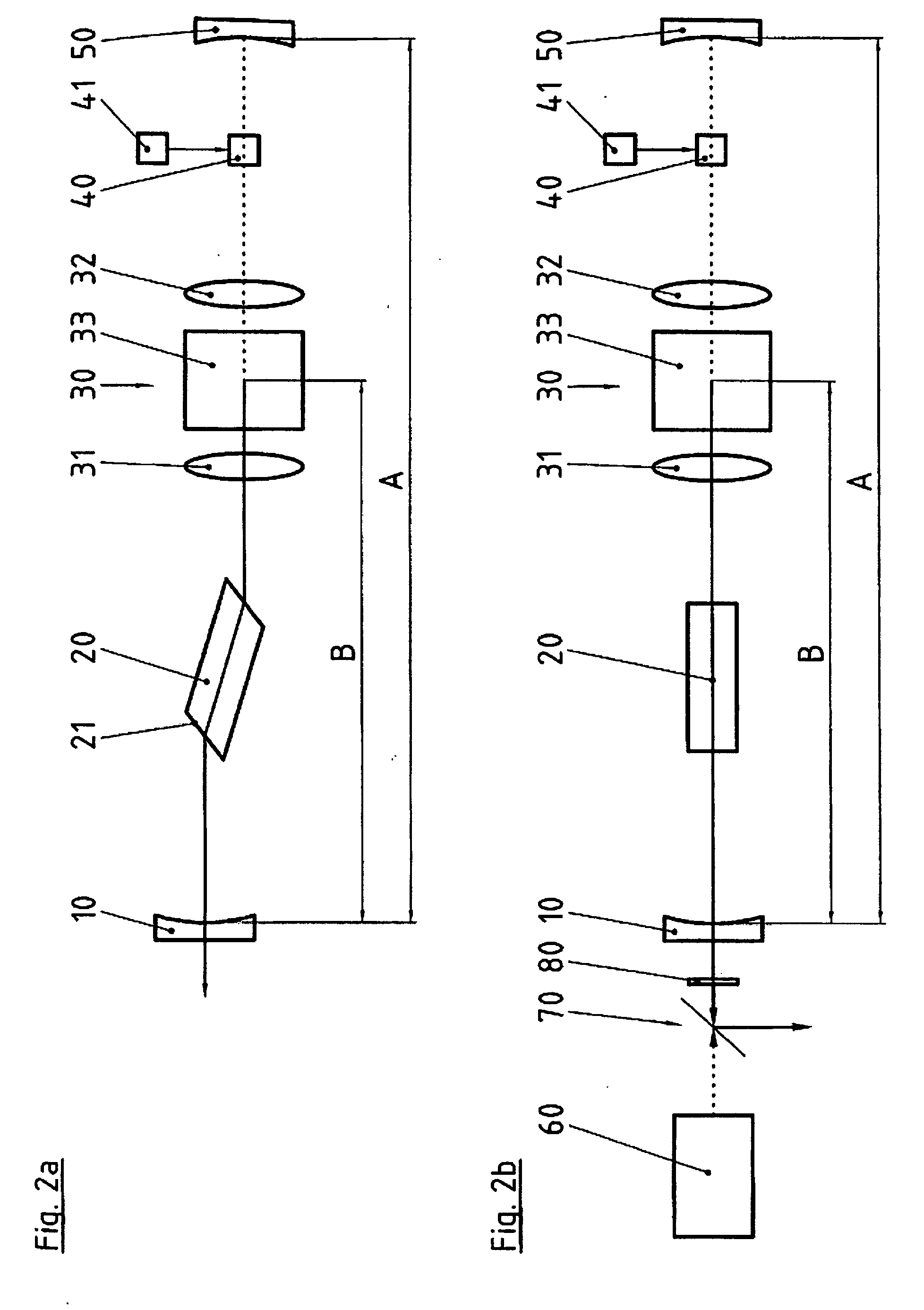
[0036]FIG. 1 shows a laser device that includes the following elements, arranged one after another along the optical axis:

[0037]outcoupling mirror 10,

[0038]a laser medium 20,

[0039]a phase-conjugate mirror (PCM) 30 based on stimulated Brillouin scattering (SBS),

[0040]a controllable modulator 40,

[0041]an end mirror 50.

[0042]The outcoupling mirror 10 and the end mirror 50 form a start cavity A, whereas the outcoupling mirror 10 and the phase-conjugate mirror 30 form a main cavity B.

[0043]FIG. 1 shows that a polarizer 90 is positioned between the outcoupling mirror 10 and the laser medium 20. In the present laser device embodiment, the polarizer causes a linearly polarized output radiation of the laser, preferred for certain applications such as, for example, the operation of a non-linear optical element.

[0044]FIG. 3 illustrates the pumping of the laser. The scale of the time axis is therefore in the micro-second range and the scale of the power is in the watt range. FIG. 4, on the othe...


PUM


Abstract

A laser device includes an outcoupling mirror, a laser medium, a phase-conjugate mirror based on stimulated Brillouin scattering, and an end mirror all arranged along an optical axis of the laser device. A controllable modulator is positioned between the phase-conjugate mirror and the end mirror. The outcoupling mirror and the end mirror form a start cavity. The outcoupling mirror and the phase-conjugate mirror form a main cavity.

Description

BACKGROUND OF THE INVENTION[0001]1. Field of Invention[0002]The disclosure relates to a laser device for the production of high-energy laser pulses.[0003]2. Description of Related Art[0004]A laser device is known from DE 41 02 409 C2 and includes the following elements, arranged one after another along the optical axis:[0005]a outcoupling mirror,[0006]a laser medium,[0007]a phase-conjugate mirror (PCM) based on stimulated Brillouin scattering (SBS),[0008]an end mirror.[0009]The outcoupling mirror and the end mirror form a start cavity, whereas the outcoupling mirror and the phase-conjugate mirror form a main cavity. With a phase-conjugate mirror, good beam quality is attained in mirror operation or operation of the main cavity. The individual light waves are precisely reflected back upon themselves and optical aberrations in the laser medium are not compounded, but almost compensated by reverse propagation of the light waves in the laser medium. The effect of a time-variable thermal...

Claims


Application Information

Patent Timeline
IPC IPC(8): H01S3/115H01S3/082
CPCH01S3/08059H01S3/115H01S3/10092H01S3/10076
Inventor EICHHORN, MARC
Owner INSTITUT FRANCO ALLEMAND DE RES & DEVS DE SAINT LOUIS
Why Eureka
Try Eureka