Double-stack shrimp tray

Inactive Publication Date: 2009-07-30
OCEAN DUKE CORP
31 Cites 20 Cited by

AI-Extracted Technical Summary

Problems solved by technology

Although generally satisfactory, such prior art trays are not readily adap...

Method used

[0029]The tiered shrimp tray of the present invention also includes a connector plate or member 200. Referring again to FIGS. 7 and 8, the connector plate also typically comprises a single sheet of material, such as plastic, which can be thermoformed, vacuformed or the like. The connector plate 200 includes a raised outer ridge 202, typically adjacent to a perimeter thereof. As can be seen in FIGS. 7 and 8, the connector plate 200 is of reduced diameter with respect to the base plate 100, and is slightly smaller or of approximately the same diameter as the upp...

Benefits of technology

[0005]The present invention is embodied in a simple, easy-to-make, tiered serving tray that presents shrimp and condiments in an appealing fashion. The present invention, as will be more fu...

Abstract

A tiered shrimp food tray including a sheet of material forming a base tray having an outer ridge, a support ridge formed concentric to and in spaced relation to the outer ridge. An inner ridge and a base surface cooperatively define a central well which supports a condiment cup. A ring of shrimp is arranged on the support ridge of the base tray. A connector plate interconnects the base tray with an upper tray. The upper tray includes an outer ridge and a support ridge spaced from one another. A second condiment cup is disposed within a well of the upper tray. A ring of shrimp is arranged on the support ridge of the upper tray.

Application Domain

Ready-for-oven doughsOther accessories +4

Technology Topic

EngineeringPrawn +2

Image

  • Double-stack shrimp tray
  • Double-stack shrimp tray
  • Double-stack shrimp tray

Examples

  • Experimental program(1)

Example

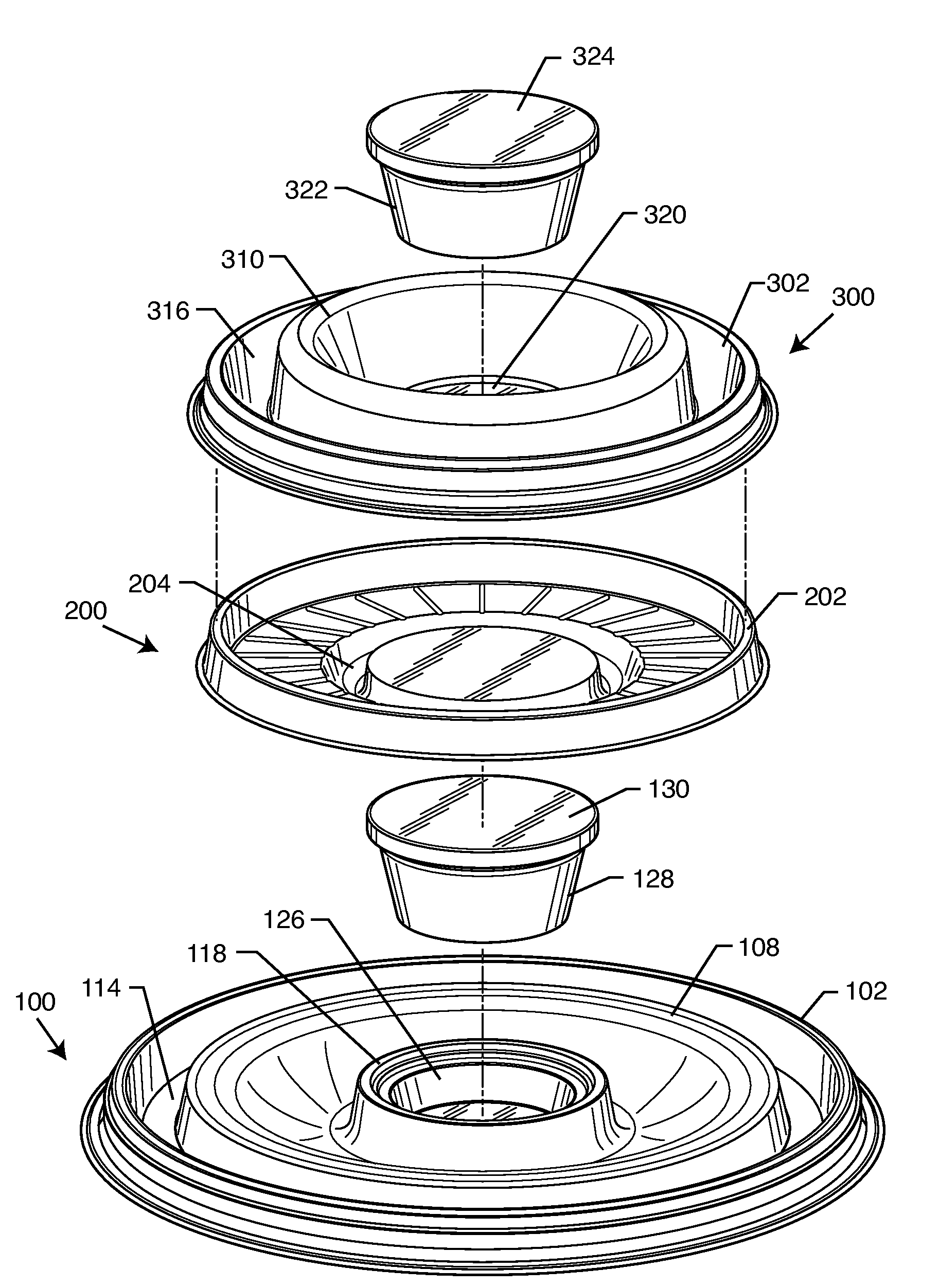
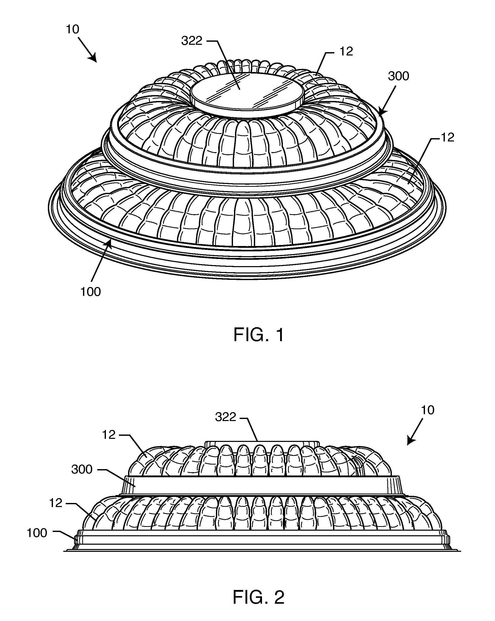
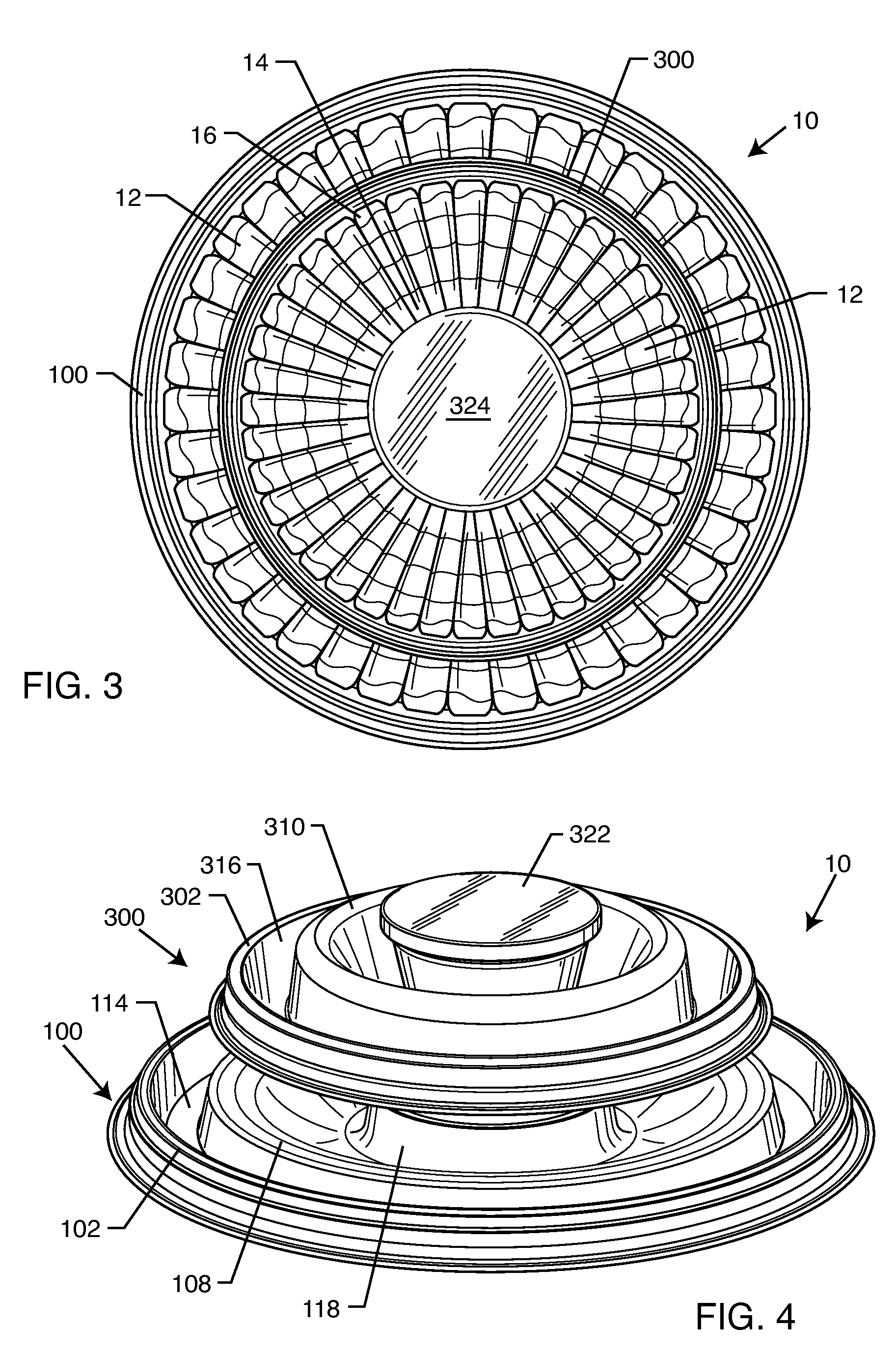
[0024]As shown in the accompanying drawings, for purposes of illustration, the present invention resides in a tiered shrimp tray, generally referred to by the reference number 10. The double-stack shrimp tray 10 of the present invention is particularly adapted for packaging, shipping, storing and serving frozen shrimp. As will be more fully described herein, the shrimp tray 10 of the present invention presents an aesthetically appealing presentation of frozen shrimp, and enables the end user to purchase two shrimp trays in a single package for placement at different locations to serve party guests.
[0025]With reference now to FIGS. 1-3, the double-stack, tiered shrimp tray 10 in its final assembled form is shown. A base tray 100 supports a plurality of shrimp 12 formed in a ring-like structure. An upper tray 300, which is of reduced diameter with respect to the lower tray 100 also supports a plurality of shrimp 12 which are arranged side-by-side to form a ring structure on the upper tray 300. As will be more fully described herein, the upper tray 300 is removably associated with the lower tray 100, such that the trays 100 and 300 can be separated from one another during use.
[0026]With reference now to FIGS. 4-7, the tiered shrimp tray 10 of the present invention is shown without the arrangement of shrimp thereon. In FIG. 4, the various components of the tiered tray 10 are shown in an assembled state. FIGS. 6 and 7 are exploded views of the shrimp tray 10.
[0027]With particular reference now to FIGS. 7 and 8, the base tray 100 is typically comprised of a single sheet of material, such as a single sheet of plastic which may be made, for example, by thermoforming or vacuforming, or any other known manufacturing method. Preferably, the base tray 100 is of a circular configuration, although it is not limited to such. The base tray 100 includes an outer ridge 102 which is typically annular in configuration. The outer ridge 102 is defined by an outer wall 104 and an inner wall 106 which are connected at a top portion thereof, and typically spaced apart from one another at a lower portion thereof, as illustrated in FIG. 8. A support ridge 108 is formed generally concentric to and in spaced-apart relation to the outer ridge 102. The support ridge 108 is defined by an outer wall 110 and a connected inner wall 112. The inner wall 112 is sloped so as to support the shrimp 12 thereon. The space between the outer ridge 102 and the support ridge 108 defines a gap or groove 114, which includes a base surface 116 extending between the outer ridge 102 and the support ridge 108. Typically, the support ridge 108 and the base surface 116 are annular in configuration.
[0028]An inner ridge 118 is formed generally concentric to and in spaced-apart relation to the support ridge 108. The inner ridge 118 is defined by an outer wall 120 and an inner wall 122. The inner wall 122 extends upwardly and generally encircles a central base surface 124. The inner ridge 118 and the central base surface 124 cooperatively define a well 126. A condiment cup 128 is sized and configured so as to be received within the well 126. Preferably, the condiment cup 128 includes a lid 130.
[0029]The tiered shrimp tray of the present invention also includes a connector plate or member 200. Referring again to FIGS. 7 and 8, the connector plate also typically comprises a single sheet of material, such as plastic, which can be thermoformed, vacuformed or the like. The connector plate 200 includes a raised outer ridge 202, typically adjacent to a perimeter thereof. As can be seen in FIGS. 7 and 8, the connector plate 200 is of reduced diameter with respect to the base plate 100, and is slightly smaller or of approximately the same diameter as the upper plate 300 in a preferred embodiment. Typically, the outer ridge 202 is generally annular in configuration. A generally annular groove 204 is formed in the sheet of material, which extends downwardly from the base surface 206. The generally annular groove defines a cavity 208 which is sized and configured so as to receive an upper portion, typically the lid 130, of the cup 128 of the base tray 100. The cavity 208 is of a slightly larger diameter than the lid 130 such that the connector plate 200 can be easily removably received onto and away from the cup 128.
[0030]With continuing reference to FIGS. 7 and 8, the upper tray 300, similar to the lower tray 100 and connector plate 200 is preferably comprised of a single sheet of material, such as plastic, which can be thermoformed, vacuformed, etc. into the necessary configuration to achieve the purposes of the present invention. The upper plate 300 includes a raised outer ridge 302 defined by an outer wall 304 and an inner wall 306. As can be seen in FIG. 8, the outer and inner walls 304 and 306 are joined at a top portion thereof, but are spaced apart from one another at a lower portion thereof so as to form a groove 308 on a bottom surface of the upper tray 300. The groove 308 is sized and configured so as to receive the outer ridge 202 and the connector plate 200 therein, in a friction-fit manner. A support ridge 310 is formed generally concentric to and in spaced-apart relation to the outer ridge 302. It is defined by an outer wall 312 and an inner sloped wall 314. The outer and inner wall 312 and 314 are typically interconnected at a top portion thereof, and in spaced-apart relation to the bottom portion thereof, as illustrated in FIG. 8.
[0031]The outer ridge 302 and support ridge 310 define a gap or groove 316 therebetween, including a base surface 318 which extends between the inner wall 306 of the outer ridge 302 and the outer wall 312 of the support ridge 310. Typically, the upper tray 300 is generally circular, and the raised support ridge 302, base surface 318, and support ridge 310 are generally annular.
[0032]The inner sloped wall 314 of the support ridge 310 extends upwardly about a periphery of a well-based platform 320. The platform 320 and the inner wall 314 of the support ridge 310 form a well for receiving a second condiment cup 322 therein. Typically, the condiment cup 322 includes a lid 324 for retaining the condiment, typically shrimp cocktail sauce therein. It will be understood by those skilled in the art that the lids 130 and 324 of the condiment cups 128 and 322 can comprise removable lids, or can comprise plastic or foil or the like which covers and encloses the contents within the cups 128 and 322.
[0033]With reference now to FIGS. 9-11, in order to assemble the tiered tray 10 of the present invention, the cup 128 is placed within wall 126. Shrimp are arranged on the support ridge to form a ring-like structure. As shown in FIGS. 1-3, the shrimp 12 have a generally concave bottom surface which generally conforms to the support ridge 108. The tail 14 of each shrimp 12 is directed towards the inner ridge 118 and condiment cup 128. The shrimp extends over the support ridge 108, with its head portion 16 residing within groove or gap 114, so as to extend toward and typically abut the outer ridge 102. The shrimp are arranged in this manner side-by-side in order to form the ring-like structure illustrated in FIGS. 1-3.
[0034]With reference again to FIGS. 9-11, the connector plate 200 is then placed over the cup 128, such that an upper portion of the cup 128, typically the lid 130, resides within cavity 208. This is particularly illustrated in FIG. 10.
[0035]The upper tray 300 has its condiment cup 322 disposed on its central well based platform 320. A plurality of shrimp 12 are arranged in a ring-like structure, as described with respect to the base plate 100. More particularly, a bottom concave surface of the shrimp are supported by the support ridge 310. A tail end 14 of each shrimp extends towards the condiment cup 322. A head end of the shrimp 16 extends into groove or gap 316 towards the wall 306 of the raised outer ridge 302, so as to be held in place. The shrimp 12 are arranged side-by-side to form the ring-like structure illustrated in FIGS. 1-3. The upper tray 300, is then placed over the connector plate such that the outer ridge 202 of the connector plate 200 is disposed within the lower groove 308 defined by the raised outer ridge 302 of the upper tray 300. The result is a friction-fit between the cup 128 of the base tray 100 and the cavity 208 of the connector plate 200, and a frictional fit between the raised outer ridge 202 of the connector plate and the bottom surface groove 308 of the upper tray 300. This arrangement is shown in FIGS. 4, 5 and 11, without shrimp, and in FIGS. 1-3 with shrimp thereon. When fully assembled, the tiered shrimp tray is encased in plastic or the like for shipping, transport, and sale. The end user is provided with an aesthetically pleasing two-tiered, or double-stacked, shrimp tray arrangement 10. Moreover, the end user can separate the upper tray 300 from the lower tray 100 such that two distinct shrimp trays are made available to party guests and the like.
[0036]Although several embodiments have been described in some detail for purposes of illustration, various modifications may be made without departing from the scope and spirit of the invention. Accordingly, the invention is not to be limited, except as by the appended claims.

PUM

PropertyMeasurementUnit
Diameter

Description & Claims & Application Information

We can also present the details of the Description, Claims and Application information to help users get a comprehensive understanding of the technical details of the patent, such as background art, summary of invention, brief description of drawings, description of embodiments, and other original content. On the other hand, users can also determine the specific scope of protection of the technology through the list of claims; as well as understand the changes in the life cycle of the technology with the presentation of the patent timeline. Login to view more.

Similar technology patents

Ratchet wrench

ActiveUS20180222020A1easily make
Owner:ZHEJIANG YIYANG TOOL MFG +2

α/β-peptide mimics of Z-domain peptides

ActiveUS9284362B2easily modifyeasily make
Owner:WISCONSIN ALUMNI RES FOUND

Ratchet wrench

InactiveUS20190358788A1easily make
Owner:YANG CHUN WEI +1

Compressor module for compressing gas and compressor equipped therewith

ActiveUS10704567B2easily makeadditional requirement
Owner:ATLAS COPCO AIRPOWER NV

Classification and recommendation of technical efficacy words

  • easily make

Data-handling, business systems and games

InactiveUS20060030402A1competitiveness be decreaseeasily make
Owner:CHANDRAKUMAR APPUTHURAI +1

Wireless transmission method and wireless transmitter having a plurality of antennas

InactiveUS20050265477A1easily makehigh immediateness
Owner:KK TOSHIBA

Liquid crystal display device and method of driving the same

InactiveUS20120218245A1low visual qualityeasily make
Owner:SHARP KK

Pet bottle coupler

InactiveUS20050189243A1easily be separate and take aparteasily make
Owner:TOMY CO LTD

Video content creating apparatus

InactiveUS20060092487A1enhance effecteasily make
Owner:ATR ADVANCED TELECOMM RES INST INT
Why Eureka
Try Eureka