Clutch actuator and method for actuating a clutch

a technology of clutch actuator and clutch plate, which is applied in the direction of mechanical actuated clutches, fluid gearings, gearings, etc., can solve the problems of micro-movements in the clutch plate itself, inconsistent and undesired system behavior, and spring force variations

Inactive Publication Date: 2009-07-30
ZF FRIEDRICHSHAFEN AG
View PDF6 Cites 5 Cited by
  • Summary
  • Abstract
  • Description
  • Claims
  • Application Information

AI Technical Summary

Benefits of technology

[0009]The present invention is based on the knowledge that the object of the present invention may be attained in a surprisingly simple manner

Problems solved by technology

The use of a preload spring and/or pretensioning spring of this type has the disadvantage that their spring force varies depending on the clutch release path.
Thus, the pretensioning force changes subject to the wear of the clutch linings which, considering the entire life of the clutch, causes inconsistent and undesired system behavior.
A further disadvantage of using a pretensioni

Method used


Image

  • Clutch actuator and method for actuating a clutch
  • Clutch actuator and method for actuating a clutch

Examples


Embodiment Construction

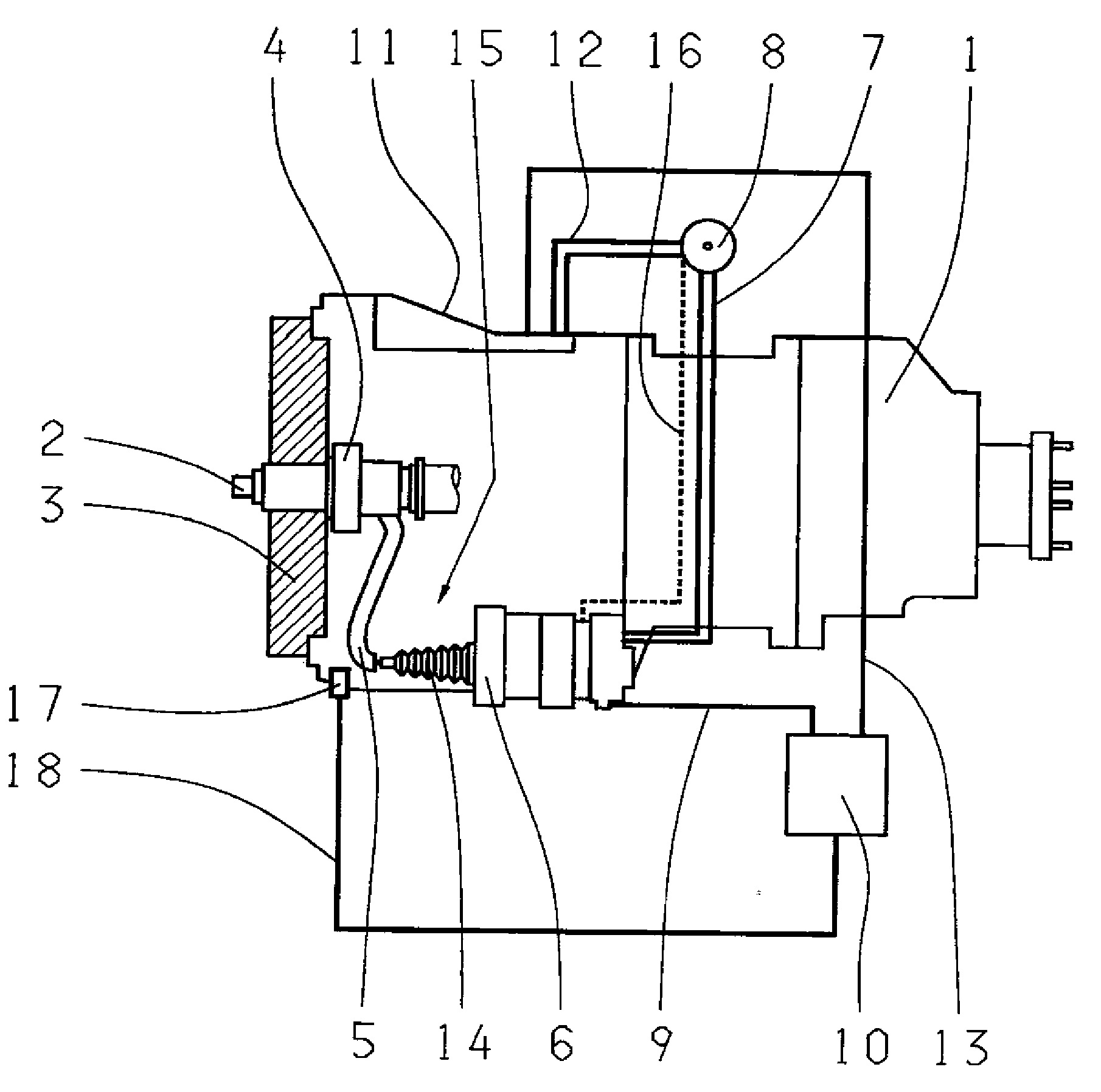
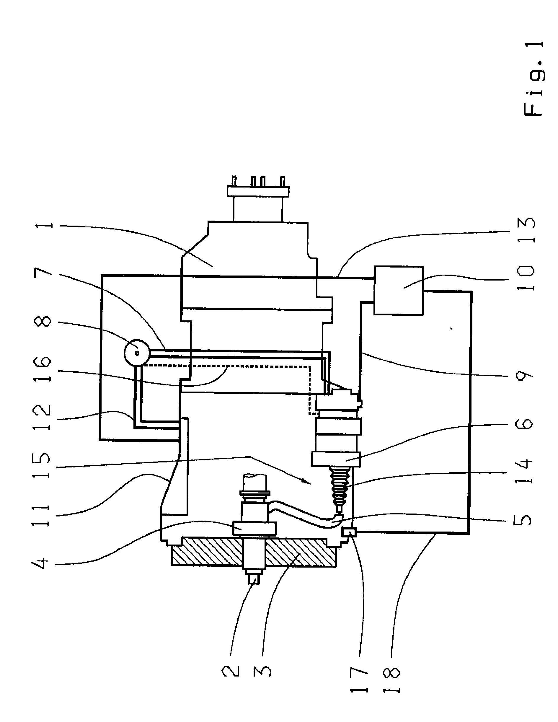
[0028]Accordingly, a FIGURE shows a schematic diagram of a transmission 1 with an exemplary embodiment of a clutch plate 6 (not shown in the drawing). A clutch 3 is arranged on the input shaft 2 of the transmission 1 so that the clutch 3 may be placed by a clutch release bearing 4, mounted on the input shaft 2, into a disengaged and an engaged state with the flywheel of the drive motor of the vehicle (not illustrated in the drawing). A lever 5 meshes with a clutch release bearing 4 and is operated by the clutch plate 6. A connection line 7 is attached to the clutch plate 6, which connects the clutch plate 6 to a reservoir 8 for the operating medium of the clutch plate 6. An electrical connection line 9 connects the clutch plate 6 to an electronic control device 10. This control device 10 may also be the main computer of the vehicle or the transmission control.

[0029]A transmission control 11, operating with a pressure medium, is arranged in the transmission 1, which is connected to t...


PUM


Abstract

A clutch plate (6), as well as a method for operating a clutch (3), between the drive motor and the transmission (1) of a motor vehicle. The clutch plate includes a cylinder with a piston (14) and an actuator (15), such that a clutch release bearing (4), arranged co-axially to the central axis of the clutch, may be operated to apply an axial pre-tensioning force on the clutch release bearing and conduct an operating medium into the clutch plate for axially displacing the piston and/or the clutch release bearing. To simplify a clutch plate of this type and enhance its utilization, the clutch plate is configured and used for generating the pre-tensioning force.

Description

[0001]This application is a national stage completion of PCT / EP2007 / 054023 filed Apr. 25, 2007, which claims priority from German Application Serial No. 10 2006 024 010.3 filed May 23, 2006.FIELD OF THE INVENTION[0002]The present invention relates to clutch plate, as well as to a method for controlling a clutch plate.BACKGROUND OF THE INVENTION[0003]Disengaging and / or releasing a clutch arranged in a power train may be achieved by way of a clutch plate arranged on a clutch bell, where the clutch plate works electrically, pneumatically or hydraulically and serves as the axial displacement of a clutch release bearing. A pneumatically operated clutch plate of this type is known from DE 100 05 086 A1 by the Applicant.[0004]In hydraulic or pneumatic clutch plates, the clutch plate essentially comprises a cylinder housing, a piston with a seal, a preload spring and, if necessary, a venting screw. The preload spring provides that a minor shift force is always present on the clutch release ...

Claims


Application Information

Patent Timeline
IPC IPC(8): F16D48/06
CPCF16D2500/3026F16D2500/501F16D48/066F16D2048/0203Y10T477/73F16D2500/1028F16D2500/10412F16D2500/1045F16D2500/3023F16D2500/1026
Inventor PETZOLD, RAINERBITZER, FRANZ
Owner ZF FRIEDRICHSHAFEN AG
Why Eureka
Try Eureka