Angular velocity sensor

a technology of angular velocity and sensor, which is applied in the field of sensors, can solve the problems of noise component being a major factor of degrading the accuracy of detection of angular velocity, affecting the detection accuracy, and difficult to generate the vibration of noise component of detection vibrator

Inactive Publication Date: 2009-08-06
CANON KK
View PDF16 Cites 14 Cited by
  • Summary
  • Abstract
  • Description
  • Claims
  • Application Information

AI Technical Summary

Problems solved by technology

In a case where the angular velocity detection is performed with high accuracy, the noise component may be a major factor of degradation of the accuracy in detection of the angular velocity.
As a result, in a case where the angular velocity is detected with high accuracy, the small noise generated in the detection signal by the above-mentioned cause (2) may degrade the detection accuracy.
Accordingly, the vibration of the noise component of the detection vibrator 70 is hardly transmitted, thereby making it difficult to generate the vibration of the noise component of the detection vibrator 70.
Thus, when the angular velocity is detected with high accuracy, the small noise due to the above-mentioned cause (1) may degrade the detection accuracy.
This may become a cause of degradation of the detection accuracy in the case where the angular velocity is detected with high accuracy (one reason for the above-mentioned cause (1)).

Method used


Image

  • Angular velocity sensor
  • Angular velocity sensor
  • Angular velocity sensor

Examples


example 1

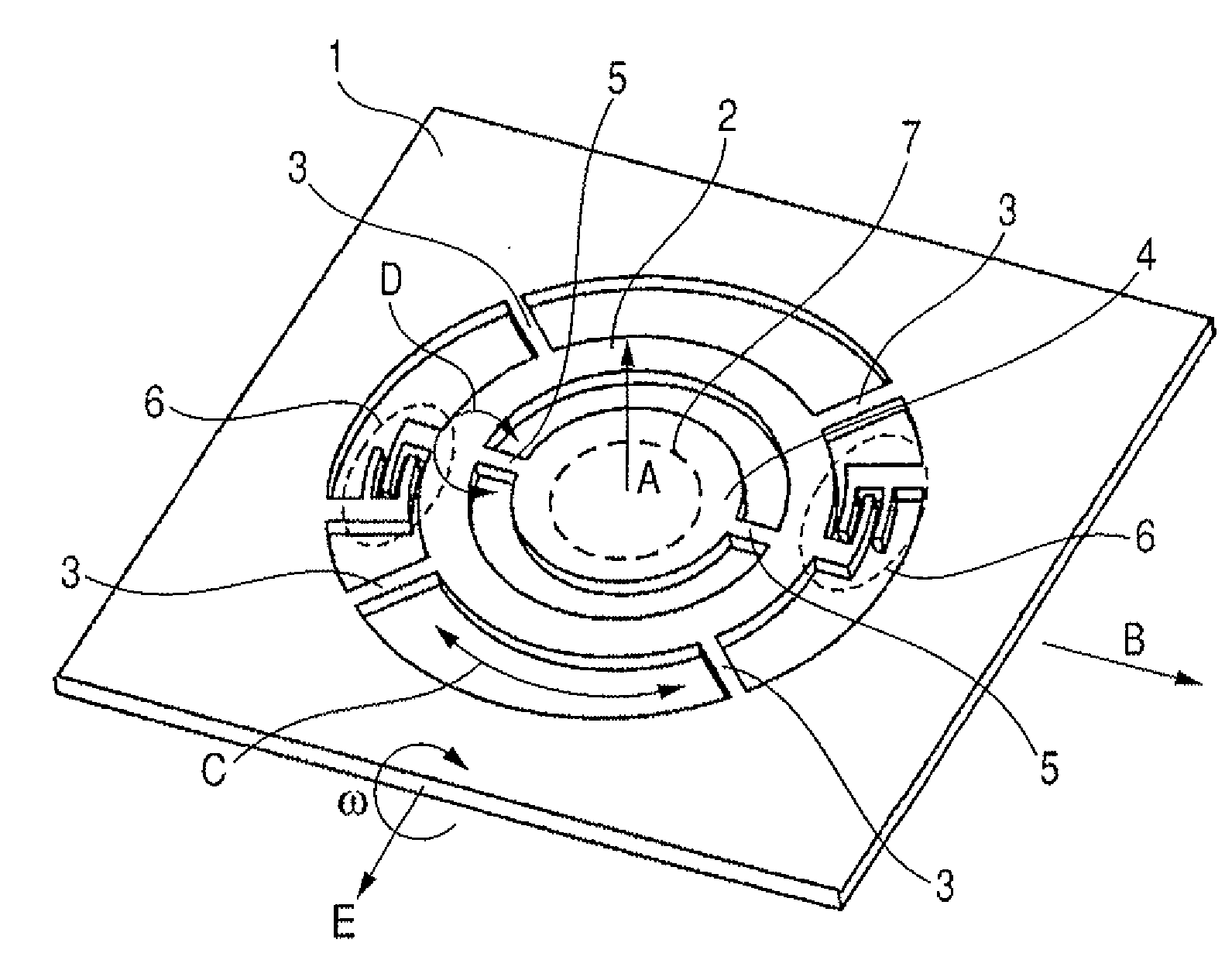
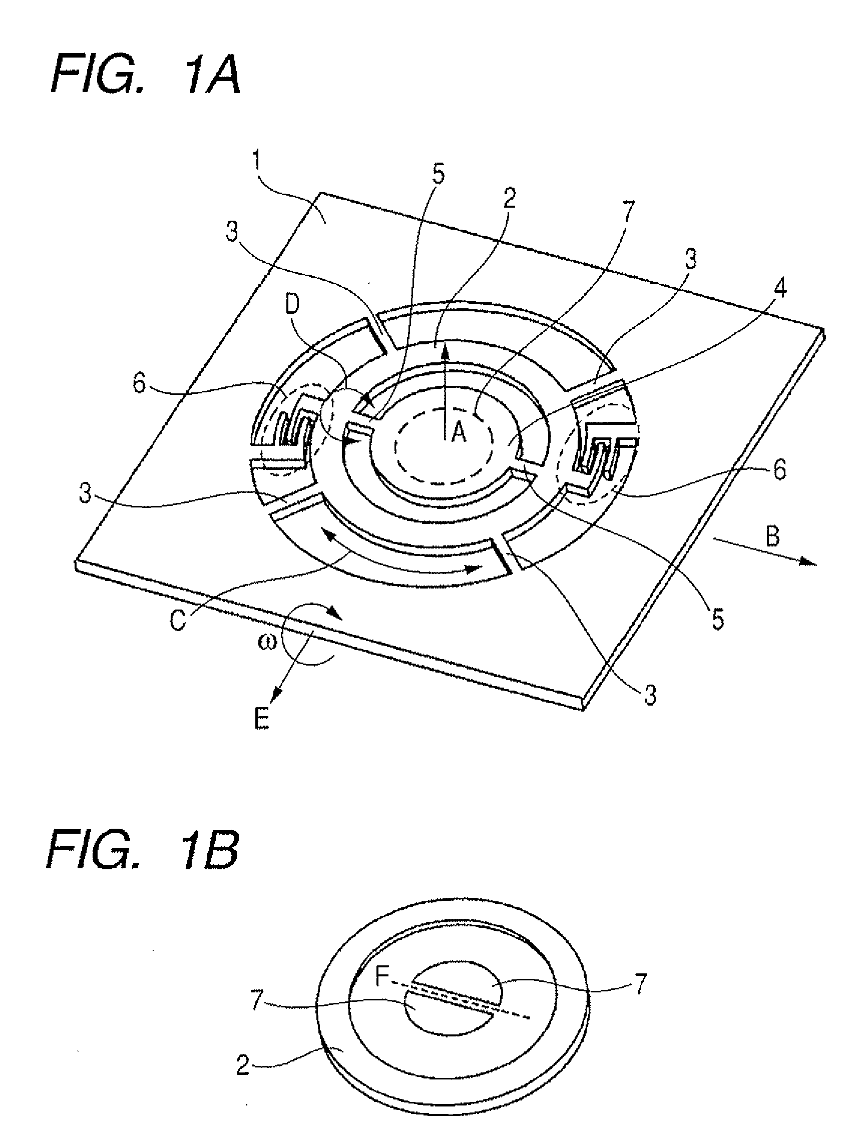
[0027]FIGS. 1A and 1B are exploded perspective views for illustrating an angular velocity sensor according to Example 1 of the present invention. As illustrated in FIGS. 1A and 1B, the angular velocity sensor includes a support substrate 1, a reference vibrator 2, a support member 3 for supporting the reference vibrator 2, a detection vibrator 4, a support member 5 for supporting the detection vibrator 4, a drive unit 6 (reference vibration generating unit) for driving the reference vibrator 2, and a detection unit 7 for detecting vibration of the detection vibrator 4.

[0028]In this example, as illustrated in FIGS. 1A and 1B, the angular velocity sensor includes the reference vibrator 2 formed of two separate members. The angular velocity sensor of this example can be produced by bonding the portion of the reference vibrator 2 illustrated in FIG. 1B to a lower portion of the reference vibrator 2 illustrated in FIG. 1A.

[0029]The annular reference vibrator 2 is supported by the substra...

example 2

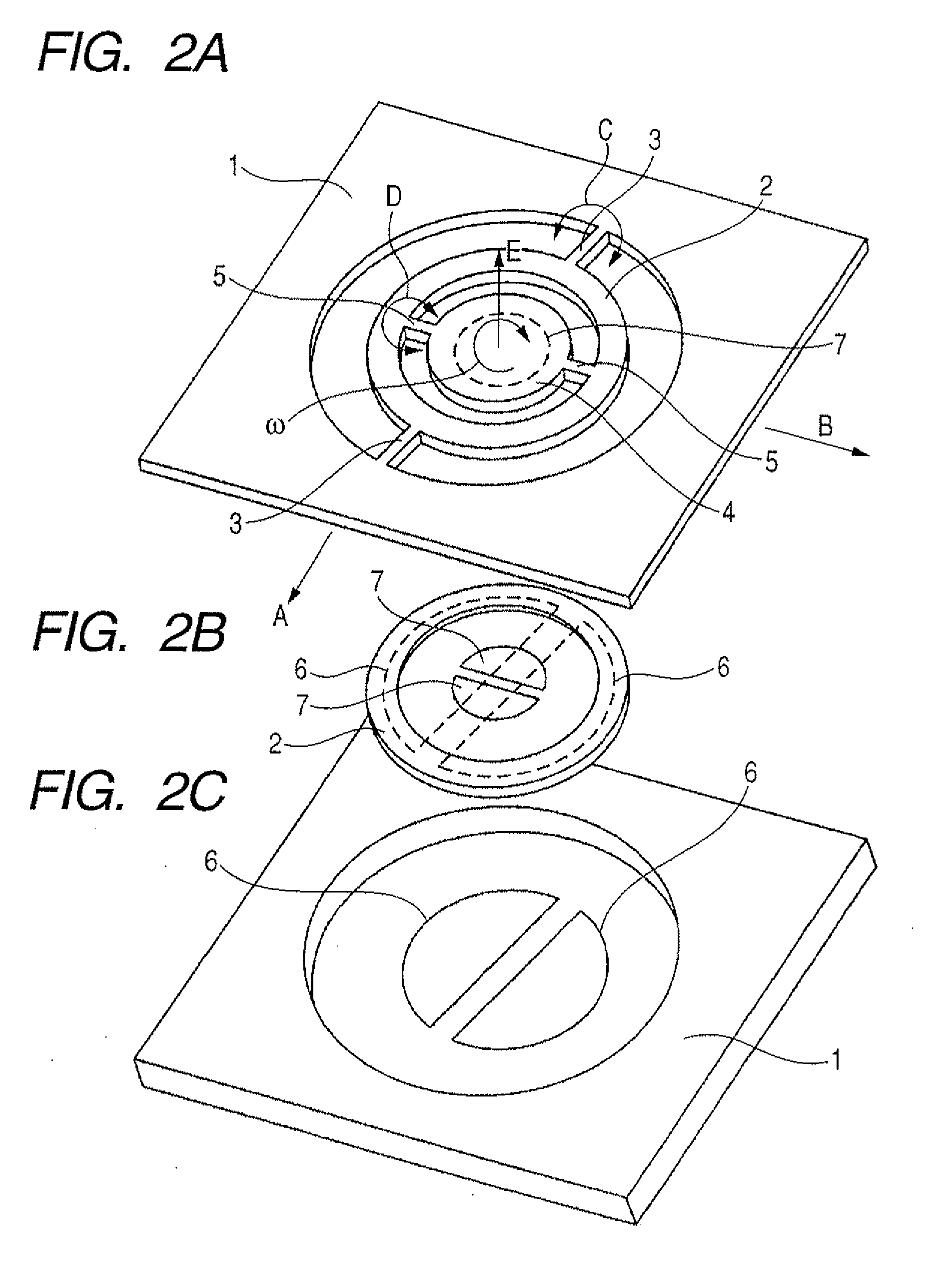
[0044]FIGS. 2A, 2B, and 2C are exploded perspective views for illustrating an angular velocity sensor according to Example 2 of the present invention. In this example, the direction (direction of the first rotation axis A) in which the reference vibration is generated is different from that of Example 1. Example 2 is similar to Example 1 except for that point.

[0045]As illustrated in FIGS. 2A, 2B, and 2C, the angular velocity sensor includes the support substrate 1, the reference vibrator 2, the support member 3 for supporting the reference vibrator 2, the detection vibrator 4, the support member 5 for supporting the detection vibrator 4, the drive unit 6 for driving the reference vibrator 2, and the detection unit 7 for detecting vibration of the detection vibrator 4.

[0046]Also in this example, as illustrated in FIGS. 2A and 2B, the reference vibrator 2 includes two separate members. The structure can be obtained by bonding the portion of the reference vibrator 2 illustrated in FIG....

example 3

[0050]FIGS. 3A and 3B are exploded perspective views for illustrating an angular velocity sensor according to Example 3 of the present invention. Example 3 is different from Example 1 in that the detection vibrator 4 has recessed portions or through-holes. Example 3 is similar to Example 1 except for that point.

[0051]Also with regard to the angular velocity sensor employing this example, there is no necessity of taking into consideration of the interference due to the vibration wobble of the reference vibrator 2. Accordingly, it is possible to dispose the portion of the reference vibrator 2 of FIG. 3B and the detection vibrator 4 with a small distance therebetween. As a result, in a case where a system for electrostatic capacity detection is used for the detection unit 7, the detection sensitivity obtained when the same angular velocity ω is input to the sensor can be improved to a large extent.

[0052]However, when the gap between the reference vibrator 2 and the detection vibrator 4...


PUM


Abstract

Provided is an angular velocity sensor including: a reference vibrator supported so as to generate reciprocating rotational vibration about a first rotation axis as a center; a detection vibrator supported by the reference vibrator so as to generate reciprocating rotational vibration about a second rotation axis, which is different from the first rotation axis, as a center; a reference vibration generating unit for allowing the reference vibrator to generate reciprocating rotational vibration; and a detection unit for detecting a displacement amount of the detection vibrator with respect to the reference vibrator, which is in association with the reciprocating rotational vibration of the detection vibrator.

Description

TECHNICAL FIELD[0001]The present invention relates to a sensor for detecting an angular velocity.BACKGROUND ART[0002]Up to now, a vibration type angular velocity sensor using micro-electro-mechanical systems (MEMS) has been proposed. The vibration type angular velocity sensor employs a system in which a Coriolis force (also referred to as “deflecting force”; hereinafter, referred to as “Coriolis force”) generated when an angular velocity, which is an object to be detected, is input to the sensor from an outside, is detected as a displacement of vibration of a vibrator, while the vibrator is allowed to generate reference vibration with a predetermined amplitude. A direction of the Coriolis force is determined by a direction of the reference vibration and by a direction of the angular velocity. Accordingly, it is necessary that the vibrator have a structure in which the vibrator can easily generate vibration in the direction of the reference vibration and also in the direction of the ...

Claims


Application Information

Patent Timeline
Patent Type & Authority Applications(United States)
IPC IPC(8): G01C19/56
CPCG01C19/5712G01C19/56H01L29/84
Inventor KANDORI, ATSUSHIMAJIMA, MASAONAGAE, KENICHI
Owner CANON KK
Why Eureka
Try Eureka