Rotational vibration (RV) can result from random seek activity among a cluster of HDDs, and the customers have become concerned over the potential for performance degradation.
However, cost effective sensing of the rotational vibration (RV) velocity or acceleration is a problem, which the conventional structures have not found a solution to yet.
Therefore, a computer frame is a compliant object which makes it susceptible to vibration.
Such a mounting configuration makes a disk drive vulnerable to vibration excited by internal or external sources.
The corresponding reaction torque on the base-plate causes transient rotational vibration that can be detrimental to the positioning accuracy of the read / write heads.
However, the presence of
random vibration impacts the track following precision (and, slightly less, the settle-out performance).
A major obstacle to raising the
track density is inadequate head positioning accuracy in the presence of vibration disturbances.
Due to
exponential growth in TPI, positioning the read / write elements over a track has become a major challenge.
When not compensated, a track following error of 15% of the track
pitch can be detrimental to a disk drive's "soft" and "hard" error rate performance.
However, a
mount design optimized to decouple internal spindle vibration as disclosed by U.S. Pat. No. 5,400,196, remains susceptible to external input vibration.
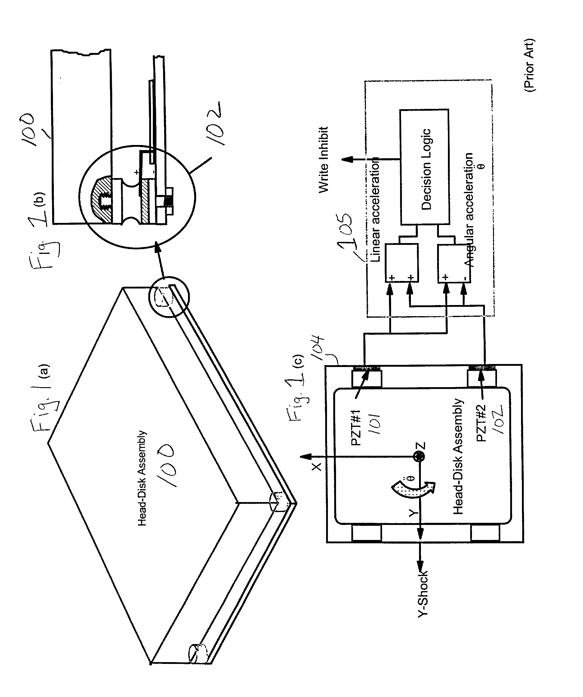
A key challenge in the use of PZTs is that they are sensitive to strain along multiple axes, and therefore they respond to vibration inputs in addition to the theta-dynamics.
To produce
high fidelity signals in the range of 100-1000 Hz, the size of a PZT configuration must be large and such a design is not compatible with the electrical card height and manufacturing requirements in a disk drive.
On the other hand, reducing the PZT volume produces poor
signal quality (i.e., particularly the
signal drift in the
low frequency range (.about.100 Hz) is not easily stabilized).
Sudden drift in a PZT
signal can cause undesirable write-abort condition.
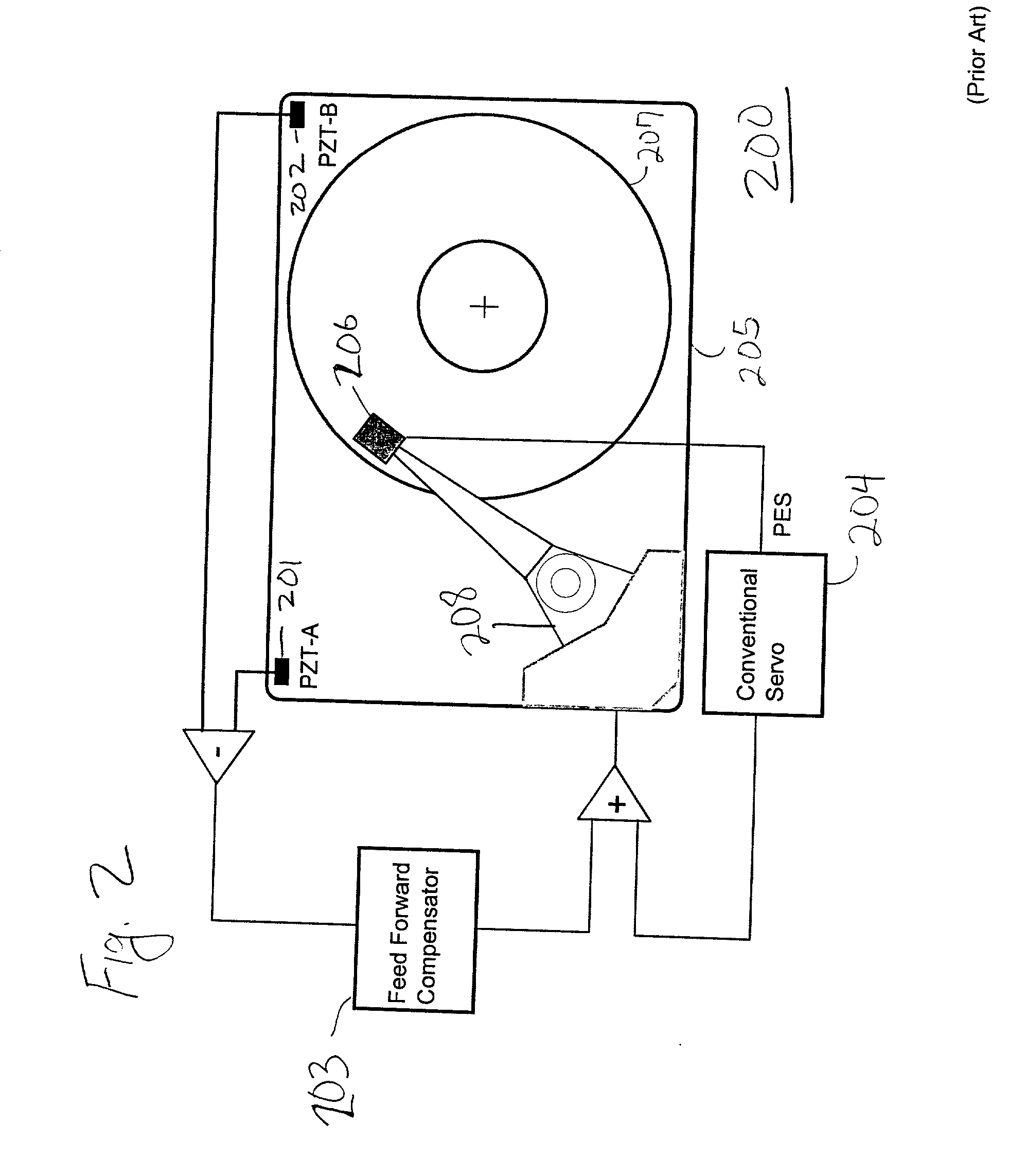
Use of dual PZTs further complicates the problem of matching the individual PZT
gain and thermal sensitivity.
However, the stringent decoupling requirements of dynamics makes the cost of a dual PZT sensor cost prohibitive for a disk drive application.
However, sensor size, bandwidth and cost are considered to be limitations of a microelectromechanical sensor (MEMS).
Thus, the conventional sensors have been unable to deal adequately with the problem of
random vibration, as it critically affects the track following precision of an HDD
actuator system, and no sensor has been produced with is cost effective and effective for sensing rotational vibration (RV) velocity or acceleration.
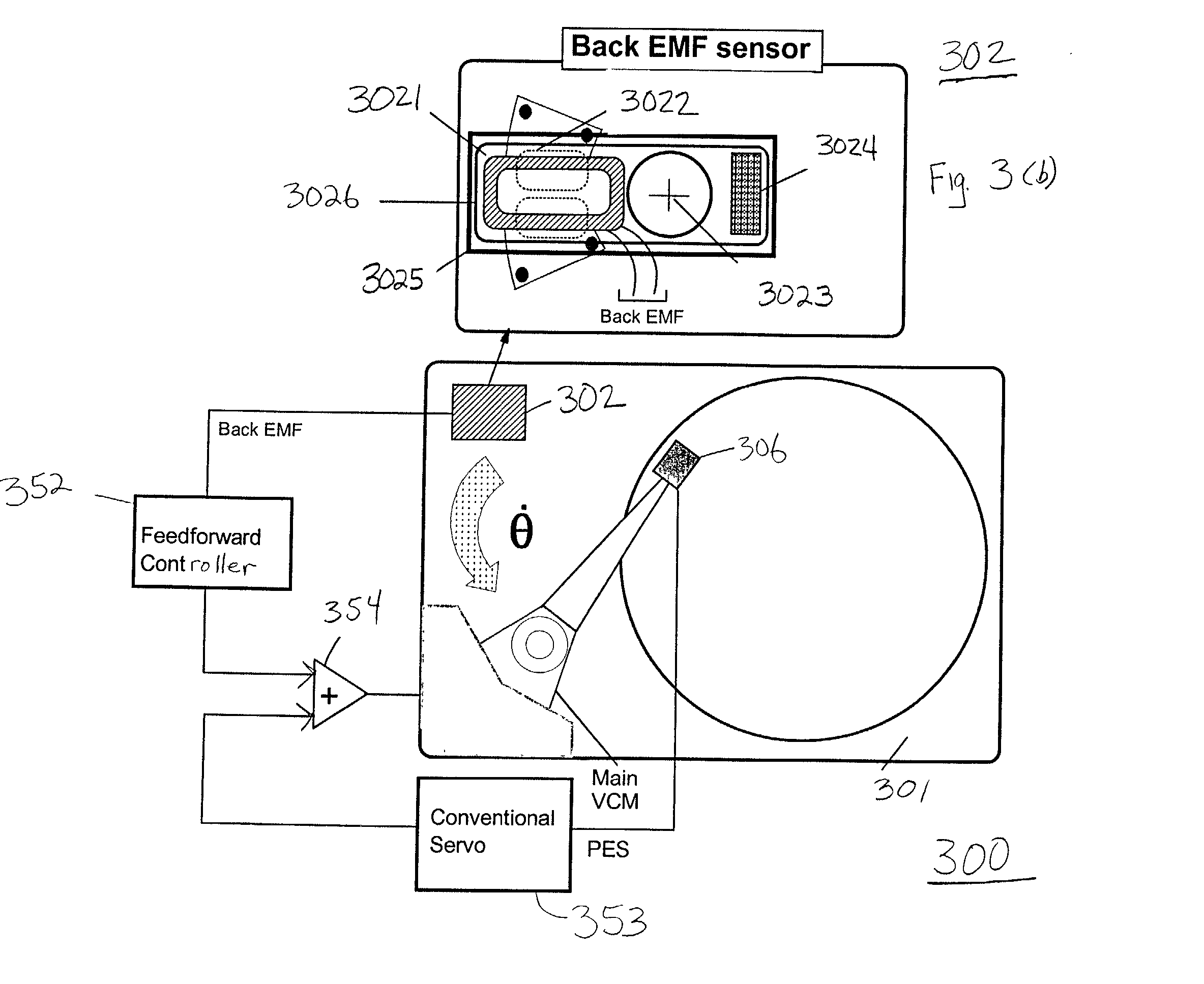
Thus, the inventors have recognized that rotational vibration of the baseplate in the plane of a disk platter causes
tracking error due to limited
servo feedback
gain.

