
Magnetic recording disk drive with multiple feedforward controllers for rotational vibration cancellation

a magnetic recording and controller technology, applied in the direction of magnetic recording, recording head arrangement, instruments, etc., can solve the problems of single feedforward controller design for rv cancellation that cannot optimally reject such a wide variety of external disturbances

Inactive Publication Date: 2008-05-20
HITACHI GLOBAL STORAGE TECH NETHERLANDS BV
View PDF21 Cites 16 Cited by
  • Summary
  • Abstract
  • Description
  • Claims
  • Application Information

AI Technical Summary

Benefits of technology

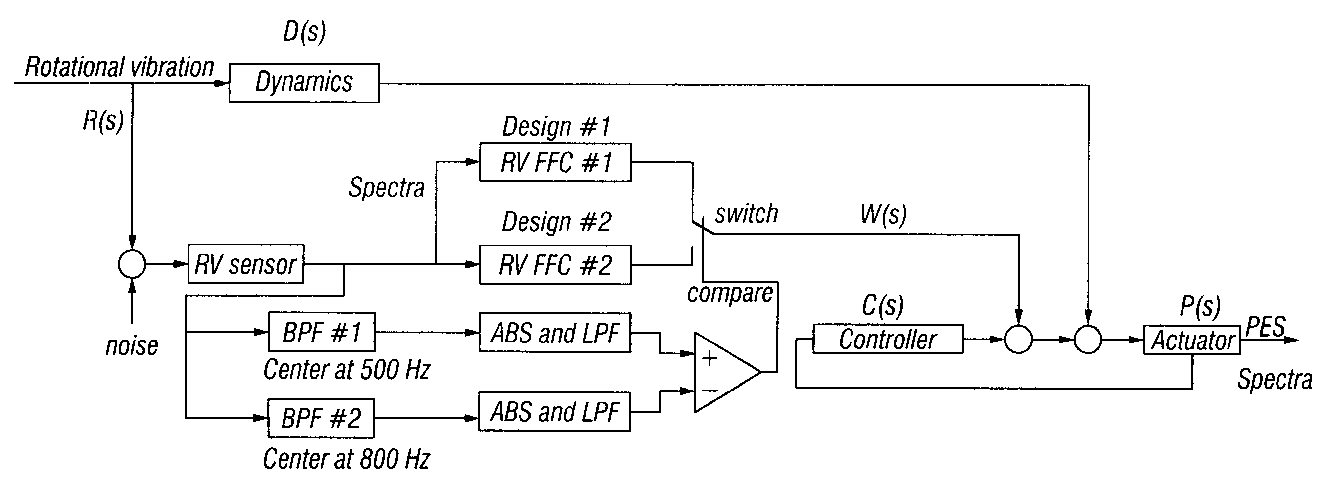
"The invention is a disk drive with multiple feedforward controllers that can handle different types of rotational vibration. Each feedforward controller is designed to cancel out a specific type of vibration. The actual vibration spectrum that affects the disk drive is determined, and the proper feedforward controller is selected to generate a compensation signal to cancel out the vibration. The feedforward controller that produces the best vibration cancellation is chosen as the appropriate one. The invention allows for better vibration cancellation and improved performance of the disk drive."

Problems solved by technology

Disk drives experience rotational vibration and disturbance forces during normal operation.
These disturbances arise internally, such as from motion of the VCM actuator, as well as externally, such as from shocks to the frame supporting the disk drive or from the movement of other disk drives when the drives are mounted together in a disk array system.
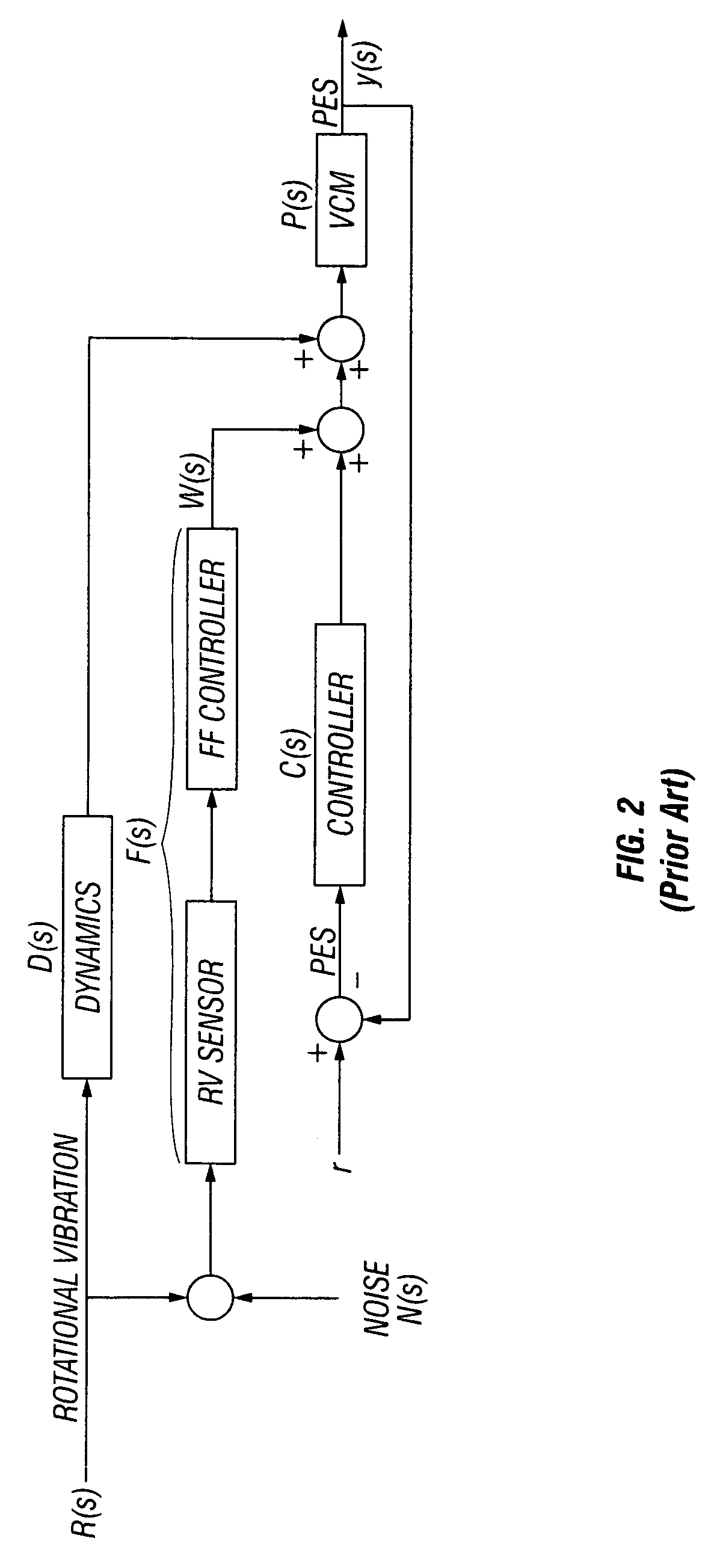
Consequently, a single feedforward controller design for RV cancellation can not optimally reject such a wide variety of external disturbances.

Method used


Image

  • Magnetic recording disk drive with multiple feedforward controllers for rotational vibration cancellation
  • Magnetic recording disk drive with multiple feedforward controllers for rotational vibration cancellation
  • Magnetic recording disk drive with multiple feedforward controllers for rotational vibration cancellation

Examples


Embodiment Construction

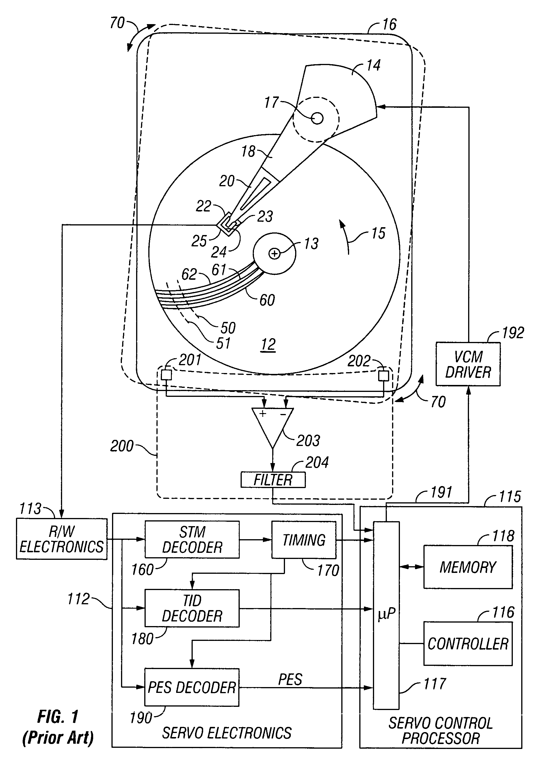
[0022]FIG. 1 is a block diagram of a magnetic recording HDD according to the prior art. The disk drive includes a magnetic recording disk 12 that is rotated about an axis of rotation 13 in direction 15 by a spindle motor (not shown) mounted to the disk drive housing or base 16. The disk 12 has a magnetic pattern in the recording layer that defines concentric data tracks, such as typical tracks 50, 51, and servo sectors, such as typical servo sectors 60, 61, 62. The servo sectors extend generally radially across the concentric data tracks so that each data track has a plurality of equally-angularly spaced servo sectors that extend around the track. Each of the servo sectors in a data track contains a servo timing mark (STM) that indicates the start of the servo sector, a track identification (TID) code, and a portion of a pattern of magnetized blocks or high-frequency bursts that are decoded to provide a head position error signal (PES).

[0023]The disk drive also includes an actuator ...


PUM

PropertyMeasurementUnit
frequencyaaaaaaaaaa
frequencyaaaaaaaaaa
center frequencyaaaaaaaaaa

Abstract

A disk drive has multiple feedforward controllers for handling external disturbances, such as rotational vibration (RV), that have different external disturbance frequency spectra. Each feedforward controller is designed to be optimal for a canceling a specific associated RV spectrum. The actual RV spectrum acting on the disk drive is determined and the proper feedforward controller is then selected and used to generate a compensation signal for canceling the RV. Each feedforward controller may be tested when the disk drive is experiencing the RV, and the resulting compensation signal and PES measured. The feedforward controller that produces the best external disturbance cancellation is then selected as the feedforward controller. A signal from a RV sensor may be used to detect the peak frequency of the actual RV spectrum. This detected peak frequency is then matched to a peak frequency in a plurality of peak frequencies in a lookup table, and the feedforward controller associated with the matching peak frequency is selected as the feedforward controller.

Description

BACKGROUND OF THE INVENTION[0001]1. Field of the Invention[0002]This invention relates generally to disk drives, and more particularly to a magnetic recording disk drive that includes a system for canceling the effects of rotational vibration.[0003]2. Description of the Related Art[0004]Magnetic recording hard disk drives (HDDs) use an actuator, typically a rotary voice-coil-motor (VCM) type of actuator, for positioning the read / write heads on the data tracks of the recording disks. The disk drive has a servo control system that receives a position error signal (PES) from servo positioning information read by the heads from the data tracks and generates a VCM control signal to maintain the heads on track and move them to the desired track for reading and writing of data.[0005]Disk drives experience rotational vibration and disturbance forces during normal operation. These disturbances arise internally, such as from motion of the VCM actuator, as well as externally, such as from shoc...

Claims


Application Information

Patent Timeline
Patent Type & Authority Patents(United States)
IPC IPC(8): G11B5/596
CPCG11B19/04
Inventor SEMBA, TETSUOWHITE, MATTHEW T.TZOU, KEVIN I.
Owner HITACHI GLOBAL STORAGE TECH NETHERLANDS BV
Learn More