
Optical inner surface measuring device

a measuring device and optical inner surface technology, applied in the field of optical inner surface measuring devices, can solve the problems of large amount of runout or non-repeatability, disable the acquisition of true measurement values, and no image data is captured, so as to remove image distortion or vibration

Active Publication Date: 2016-11-24
NAMIKI PRECISION JEWEL CO LTD
View PDF7 Cites 14 Cited by
  • Summary
  • Abstract
  • Description
  • Claims
  • Application Information

AI Technical Summary

Benefits of technology

The present invention allows for accurate and precise observation of the inner surface of a tube or cylinder. It does this by removing distortions and vibrations caused by uneven rotation of the light beam. This technology results in high-accuracy measurements of the inner diameter and inner peripheral surface.

Problems solved by technology

According to this configuration, however, an electric wire or wiring substrates (22) and (23) in a motor (1) block the rotationally radiated light ray, and thus the 360-degree radiation cannot be completely conducted to cause some portions from which no image data is captured.
In this configuration, when the hollow motor (26) rotates at a high speed, the rotation shaft causes a large amount of runout or non-repeatable runout so as not to satisfy the requisite accuracy for the inner shape measurement sensor.
Therefore, distortion or noise appears on the collected cross-section shape data of the inner peripheral surface of the target object, which disables acquisition of true measurement values.
However, JP-A-5-180627 does not propose a mechanism configured to radiate rotationally a light beam.
Therefore, when the rotational motor for beam radiation rotates at a high speed, the rotation shaft causes runout or non-repeatable runout, and noise or distortion appears on the collected cross-section shape data of the inner peripheral surface of the target object, which disables acquisition of true measurement values.

Method used


Image

  • Optical inner surface measuring device
  • Optical inner surface measuring device
  • Optical inner surface measuring device

Examples


example 1

[0057]A first embodiment of the optical inner surface measuring device according to the present invention will be described. FIGS. 1 to 10 illustrate the embodiment of the optical inner surface measuring device according to the present invention.

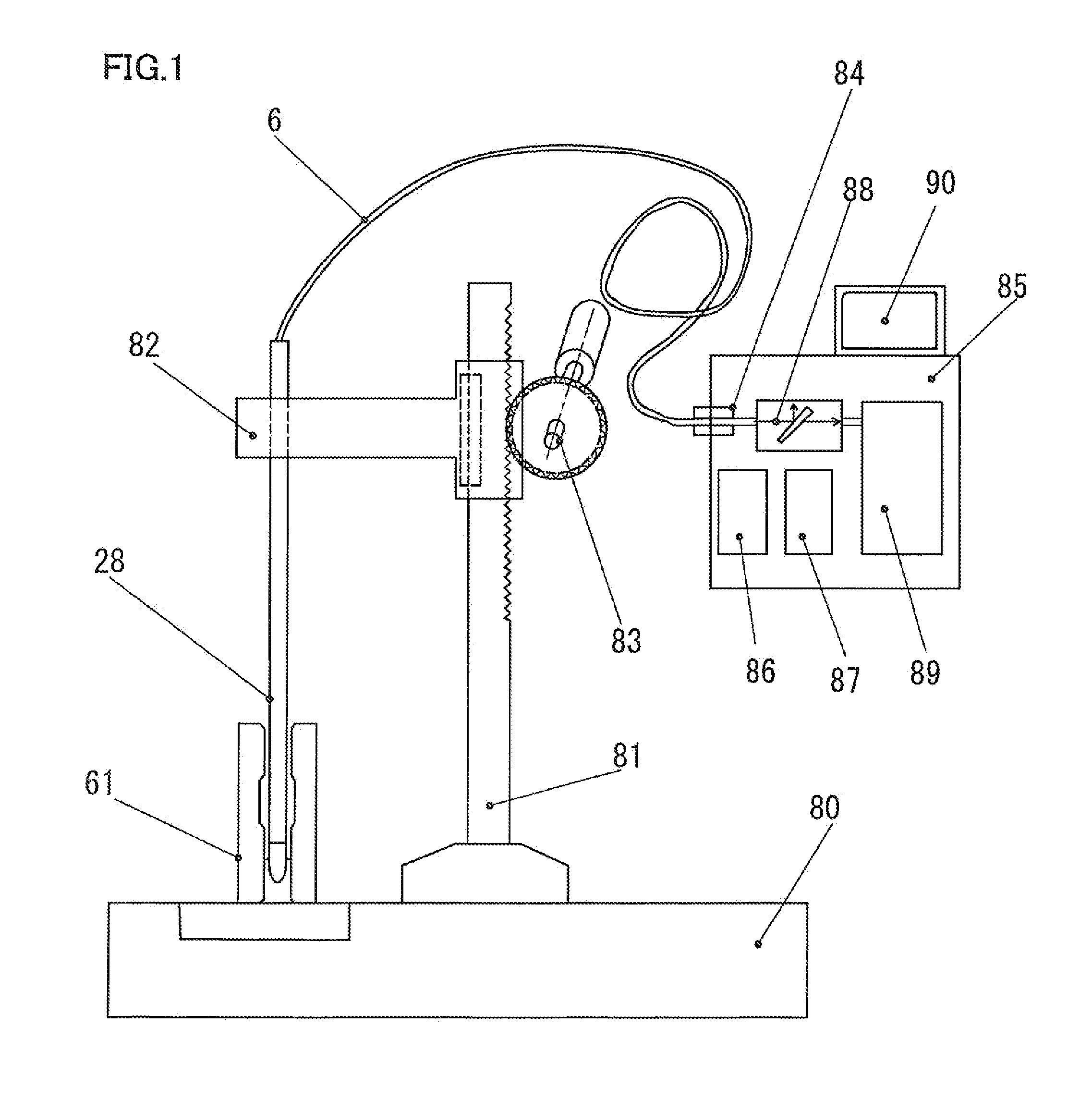
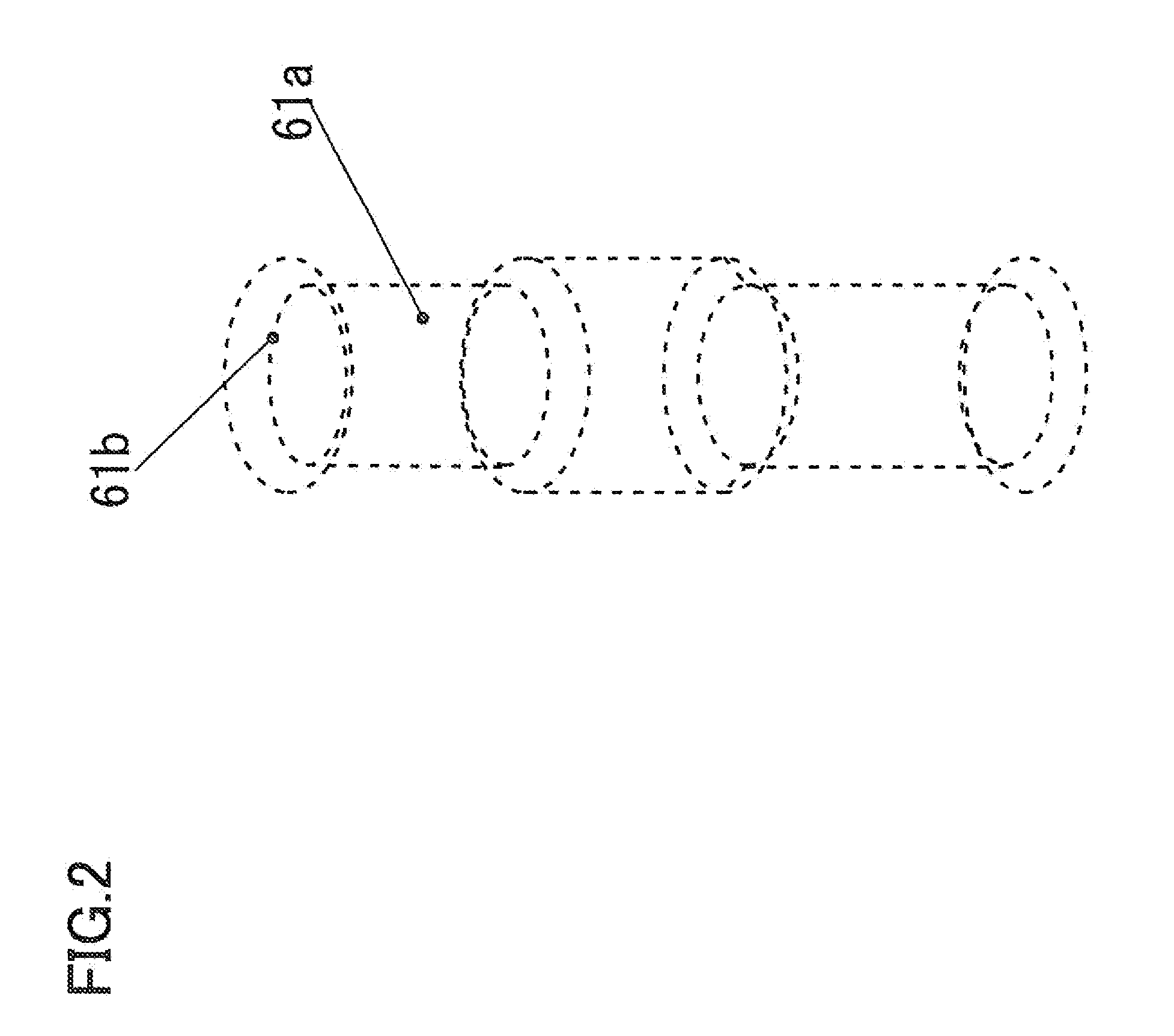
[0058]FIG. 1 illustrates an optical inner surface measuring device according to the first embodiment of the present invention. A stand 81 is fixed to a base 80, and a slider 82 and a probe 28 are vertically moved by a slider motor 83. A target object 61 is set on the base 80, and the probe 28, 58 comes in and out of a deep hole 61a in the target object 61 illustrated in FIG. 2. A light ray having entered into the probe 28, 59 passes through a tube 6 and a connection unit 84 of a measuring machine main body 85, and enters into an optical interference analysis unit 88. The light ray is then analyzed by a computer 89, and an image is displayed on a monitor 90.

[0059]The optical inner surface measuring device has more than one, for example, eight...

example 2

[0099]FIGS. 12 to 16 illustrate a second embodiment of an optical inner surface measuring device according to the present invention.

[0100]FIG. 12 is a cross-sectional view of an optical inner surface measuring device according to the second embodiment of the present invention. A fixation-side optical fiber 31 is inserted into a sufficiently long hole of a tube 36 to guide a light ray from the back end side to the front end side of a probe 59, and is fixed by an optical fiber fixture 34.

[0101]A rotation-side optical fiber 32 is rotatably provided at the leading end side of the fixation-side optical fiber 31. First light path conversion units 33a and 33b formed from almost flat mirrors or the like are rotatably attached to the leading end of the rotation-side optical fiber 32 independently from the rotation-side optical fiber 32 by a first motor 42, and are configured to rotate and radiate a light ray in 360 degrees.

[0102]A second light path conversion unit 50 is attached to the leadi...

example 3

[0119]FIGS. 17 and 18 illustrate a third embodiment of an optical inner surface measuring device according to the present invention.

[0120]FIG. 17 is a cross-sectional view of the optical inner surface measuring device according to the embodiment of the present invention. The fixation-side optical fiber 1 is configured to transfer light between the leading end side (toward the light transmission member 21) and back end side of the probe 59. The fixation-side optical fiber 1 is built into the tube 36, and includes the light-collecting lens 24 such as a ball lens, for example, at the leading end side.

[0121]The first light path conversion unit 33 such as a rotational mirror with an inclined angle is provided at the leading end side of the light-collecting lens 24. The first motor 12 is rotated with voltage application from the electric wire 23.

[0122]The first motor 12 includes the first hollow rotation shaft 10 supported by the bearings 9a and 9b, in which the motor coil 7 is incorporat...


PUM


Abstract

Higher-precision measurement is achieved by an optical inner surface measuring device configured to cause a probe to enter into the inner peripheral surface or deep hole of a target object, capture and observe reflection light from the inner surface in a three-dimensional manner, and measure the accuracy of the target object. In a structure including an optical fiber built into a tube, a light path conversion unit arranged at a leading end side of the optical fiber, and a motor configured to rotationally drive the light path conversion unit, a unit for measuring the amount of runout of a rotation shaft unit of the motor is provided. Shape data on the inner peripheral surface of a target object is obtained by calculating at a computer reflection light from the target object, and is modified by displacement amount data from a displacement measurement unit to realize high-precision measurement with no measurement error resulting from runout and rotational vibration of the rotation shaft of the motor.

Description

BACKGROUND[0001]1. Technical Field[0002]The present invention relates to an optical inner surface measuring device configured to cause a probe to enter into the inner peripheral surface or deep hole of a target object, radiate a light ray to the inner surface or deep hole bottom surface, capture and observe reflection light in a three-dimensional manner, and measure the dimension and geometric accuracy of the target object.[0003]2. Description of the Related Art[0004]For example, the finished dimension and geometric accuracy of a cylinder for an automobile engine significantly influence on power performance and fuel consumption efficiency of an automobile. These finished dimension and geometric accuracy are usually measured with the use of a contact measuring device such as a roundness measuring machine, a surface roughness meter, and a length measuring machine with a linear scale. In recent years, however, there has been provided an optical non-contact measuring device for the purp...

Claims


Application Information

Patent Timeline
IPC IPC(8): G01B11/14
CPCG01B11/14G01B9/02076A61B1/00172G01B11/30G01B9/0205G01B11/12G01B11/24G01B11/2441A61B1/00165
Inventor YAMAZAKI, HIROSHIFUKUSHIMA, ERIYANAGIURA, KAZUMIASADA, TAKAFUMI
Owner NAMIKI PRECISION JEWEL CO LTD
Learn More