Method and system for time-shift based rotational vibration sensing in disk drives

a disk drive and rotational vibration technology, applied in the field of disk drives, can solve the problems of high criticality of vibration induced track following error components, computer system itself may be subject to external seismic excitation, and the accuracy of head positioning in a disk drive is prone to both self-generated vibration and vibration

Inactive Publication Date: 2003-11-27
WESTERN DIGITAL TECH INC
View PDF10 Cites 16 Cited by
  • Summary
  • Abstract
  • Description
  • Claims
  • Application Information

AI Technical Summary

Problems solved by technology

As track density continues to grow, vibration induced track following error component becomes highly critical to the operation of a disk drive.
In addition, a computer system itself may be subjected to external seismic excitations.
Head positioning accuracy in a disk drive is prone to both self-generated vibration and to vibration generated by a neighboring disk drive or other peripherals attached to the same mounting structure.
Therefore, a computer frame is a compliant object which makes it susceptible to vibration.
Such a mounting configuration makes a disk drive vulnerable to vibration excited by internal and external sources.
The corresponding reaction torque on the base-plate causes transient rotational vibration that can be detrimental to the positioning accuracy of the read / write heads.
However, the presence of random vibration impacts the track following precision, and to a lesser degree the settle-out performance.
A major obstacle to raising the track density is inadequate head positioning accuracy in the presence of vibration disturbances.
Due to exponential growth in TPI, positioning the read / write elements over a track has become a major challenge.
The mechanical components such as spindle motor assemblies are not perfectly mass-balanced, and during operation they produce harmonic vibration.
When not compensated, a track following error of 15% of the track pitch can be detrimental to a disk drive's "soft" and "hard" error rate performance.
However, a mount design optimized to decouple internal spindle vibration as covered by the U.S. Pat. No. 5,400,196, remains susceptible to external input vibration.
Another challenge in the use of PZTs is that they are sensitive to strain along multiple axes, and therefore they respond to vibration inputs in addition to the theta-dynamics.
To produce high fidelity signals in the range of 100-1000 Hz, the size of a PZT configuration must be large and such a design is not compatible with the electrical card height and manufacturing requirements in a disk drive.
On the other hand, reducing the PZT volume produces poor signal quality, and more particularly the signal drift in the low frequency range (.about.100 Hz) is not easily stabilized.
Signal stability and noise are key problems in employing a compact PZT configuration.
Sudden drift in PZT signal can cause undesirable write-abort condition.
Use of dual PZTs further complicates the problem of matching the individual PZT gain and thermal sensitivity.
However, this requirement makes the sensor cost prohibitive for a disk drive application.
Sensor size, bandwidth and cost are considered to be a limitation of a micro-electromechanical structures (MEMS) sensor.
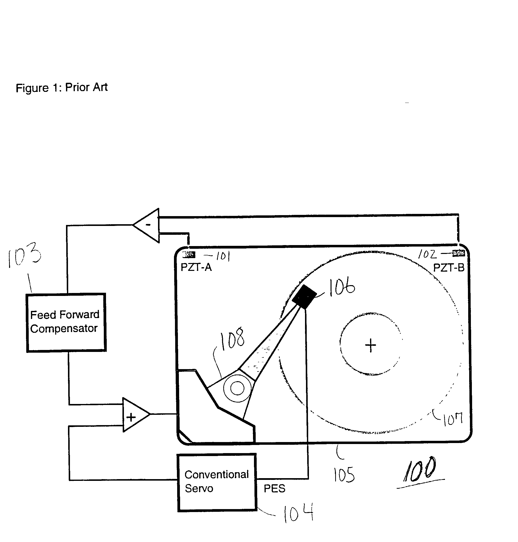
That is, the conventional techniques of using sensors such as dual piezoelectric (PZT) or electromotive force generator (EMF) to allow the servo position controller to compensate for this type of disturbance, have not been adequate or optimized.
Indeed, such techniques have required an external sensor to detect the rotational vibration, thereby making the HDD costly and complex, and there has been no scalability with the expected future increase in tracks per inch (TPI) and bits per inch (BPI).
Additionally, with multiple heads provided, there are many opportunities to detect / sense the motion, and thereby redundancy is provided.

Method used


Image

  • Method and system for time-shift based rotational vibration sensing in disk drives
  • Method and system for time-shift based rotational vibration sensing in disk drives
  • Method and system for time-shift based rotational vibration sensing in disk drives

Examples


Embodiment Construction

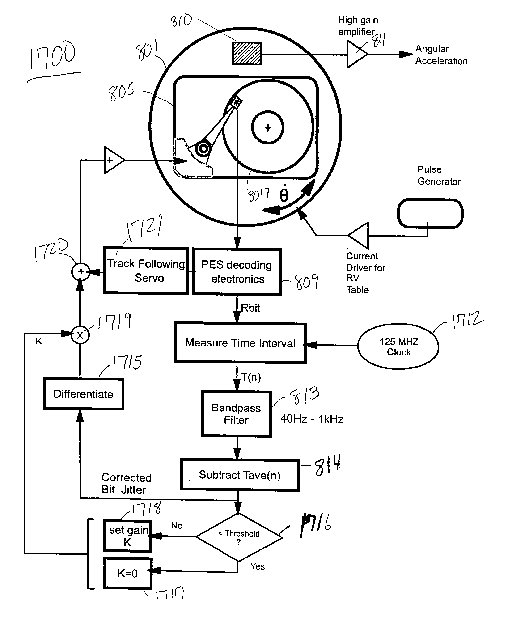
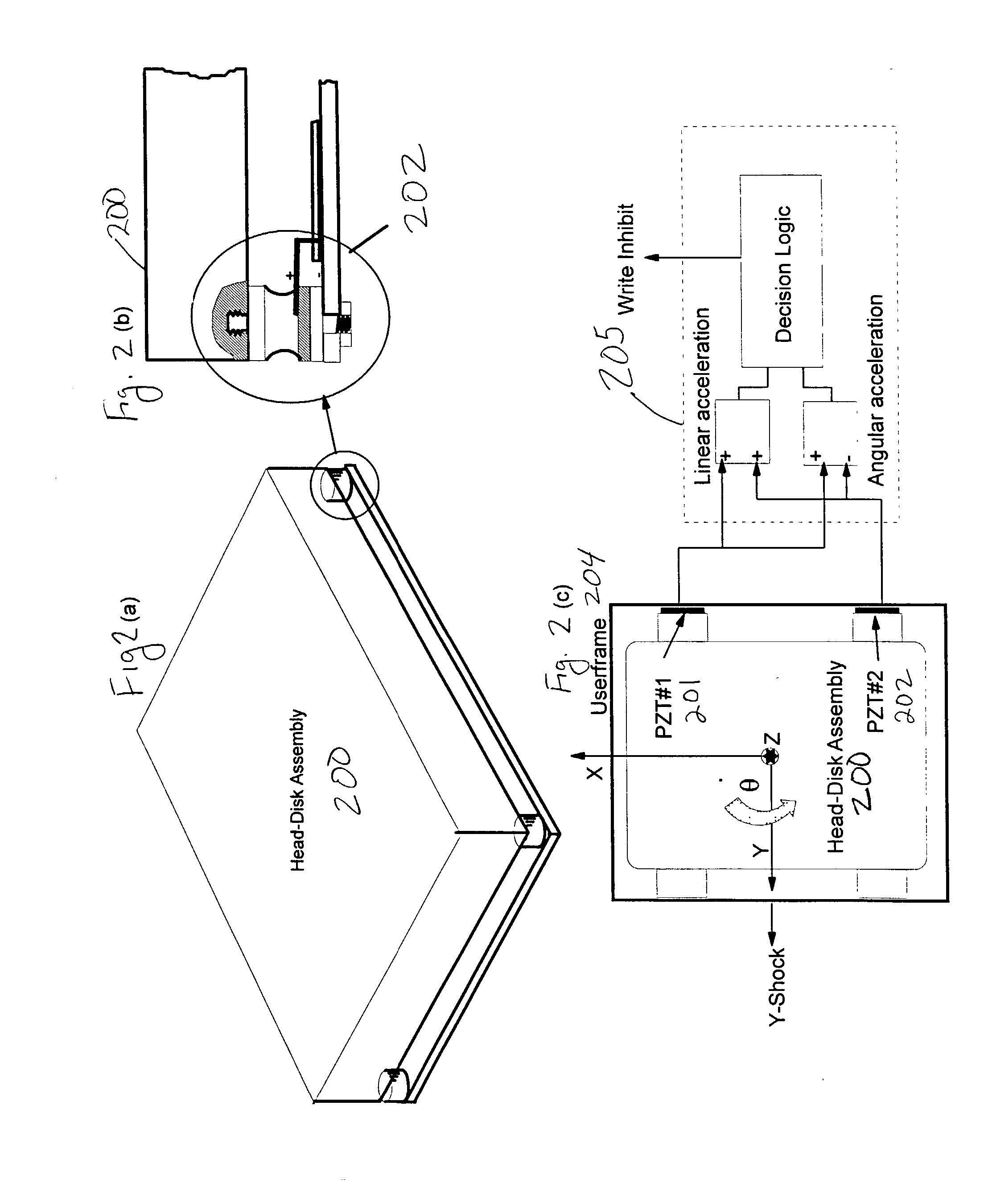
[0056] Referring now to the drawings, and more particularly to FIGS. 3-18, there are shown preferred embodiments of the method and structures according to the present invention.

[0057] Preferred Embodiment

[0058] As shown in FIG. 3, an actuator of a disk drive generates a reaction torque during a seek. In computer configurations where there are multiple drives arranged in the form of an array, the multiple reactions produced by the drives generate a vibration spectrum. The form and magnitude of a vibration (e.g., both linear and rotational) spectrum is system specific, but it tends to be a band-limited power spectrum interspersed with a finite number of harmonics.

[0059] As shown in FIG. 3, the base-plate vibration, especially along X, Y and about Z axes can contribute to TMR. A major contribution to TMR comes from rotational vibration about the Z axis (e.g., so-called theta-dynamics). The actuator mass imbalance contributes to TMR through the torque disturbance produced by the linear ...


PUM

PropertyMeasurementUnit
seek timeaaaaaaaaaa
seek timeaaaaaaaaaa
frequencyaaaaaaaaaa

Abstract

A method (and structure) senses a rotational vibration of a disk drive. The disk drive includes a rotating disk. The disk includes a plurality of reference bits across a surface thereof. The method (and structure) includes detecting the reference bits across a pattern on the rotating disk, and analyzing a time interval between adjacent ones of the reference bits.

Description

[0001] 1. Field of the Invention[0002] The present invention generally relates to a disk drive, and more particularly to a method and system for detecting rotational vibration without using an external sensor, and more particularly by measuring the time shift of the magnetic transitions (e.g., time variations or jitters, or bit variations or jitters) due to vibration alone.[0003] 2. Description of the Related Art[0004] As track density continues to grow, vibration induced track following error component becomes highly critical to the operation of a disk drive. The effective data rate throughput is degraded in the presence of rotational vibration. At high TPI (tracks per inch), the in-plane rotational vibration (theta coordinate) of a disk drive, directly impacts the TMR (track misregistration) component. A solution to this vibration challenge can be developed along several disciplines, ranging from novel mount systems to sophisticated sensors and servo algorithms.[0005] A computer s...

Claims


Application Information

Patent Timeline
Patent Type & Authority Applications(United States)
IPC IPC(8): G11B5/55G11B5/596G11B25/04
CPCG11B5/5582G11B25/043G11B5/59627G11B5/596
Inventor DANG, HIENYONEDA, ISAOUEDA, TETSUONAKAGAWA, YUZOSRI-JAYANTHA, SRI M.
Owner WESTERN DIGITAL TECH INC
Why Eureka
Try Eureka