Detecting the clogging of a fluid filter

Active Publication Date: 2009-08-06
SN DETUDE & DE CONSTR DE MOTEURS DAVIATION S N E C M A
View PDF3 Cites 14 Cited by
  • Summary
  • Abstract
  • Description
  • Claims
  • Application Information

AI Technical Summary

Benefits of technology

[0013]The invention seeks to propose a method of detecting the clogging of a filter that makes it possible

Problems solved by technology

In use, by recovering such impurities and residues, the filter clogs up progressively, and ends up preventing fluid from passing through the filter.
However, it can happen that the maintenance crew performs this maintenance operation late, possibly after the filter 20 has become completely clogged.
Under such circumstances, it is essential for the circuit to

Method used


Image

  • Detecting the clogging of a fluid filter
  • Detecting the clogging of a fluid filter
  • Detecting the clogging of a fluid filter

Examples


Embodiment Construction

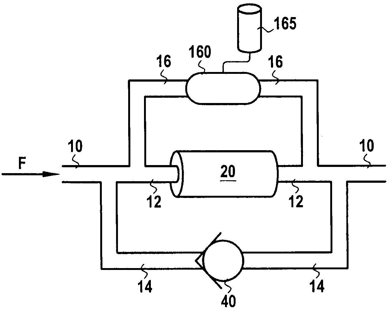
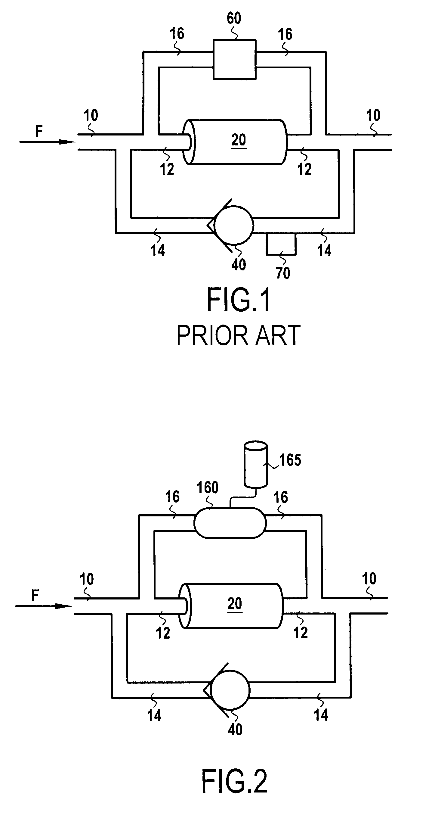
[0025]FIG. 2 shows a filter 20 mounted in a main branch 10 of a fluid circuit. By way of example, the filter 20 may be mounted in a fluid circuit of a turbomachine. The fluid may be constituted, for example, by a lubricant such as oil, or by a fuel. Upstream from the filter 20, the main branch 10 splits into two branches, a first branch 12 that extends the main branch 10 and that has the filter 20 mounted therein, and a second branch 14 that has a bypass device 40 mounted therein. Downstream from the bypass device 40, the second branch 14 rejoins the first branch 12 downstream from the filter 20 so as to reform the main branch 10, so that the bypass device 40 is mounted in parallel with the filter 20. In FIG. 2, the fluid flows from left to right as represented by the arrow F.

[0026]A sensor 160 is connected to the first branch 12 containing the filter 20, on either side of the filter 20. Thus, a third branch 16 of the fluid circuit connects the first branch 12 upstream from the filt...


PUM

PropertyMeasurementUnit
Pressureaaaaaaaaaa

Abstract

The invention relates to the field of fluid filters. It provides a method of detecting clogging of a fluid filter, which method comprises measuring, at successive sampling instants, the pressure difference ΔP from upstream to downstream across the filter, and then calculating the first time derivative {ΔP}′ of the pressure difference ΔP at different instants, and then sending a clogging signal SC representative of the filter being clogged when the first derivative {ΔP}′ is equal to zero.

Description

FIELD OF THE INVENTION[0001]The present invention relates to the field of fluid filters.[0002]More particularly, the invention relates to a method and a device for detecting the clogging of a fluid filter.BACKGROUND OF THE INVENTION[0003]A fluid circuit is generally fitted with a filter that serves to filter the fluid, i.e. to remove impurities and residues therefrom that might otherwise damage the equipment in which the fluid flows. By way of example the fluid may be a lubricant such as oil, or it may be a fuel.[0004]In use, by recovering such impurities and residues, the filter clogs up progressively, and ends up preventing fluid from passing through the filter. In order to avoid that situation, the branch of the fluid circuit having the filter mounted therein includes a bypass circuit in parallel. This configuration is shown in FIG. 1, which shows the state of the art. In the description below, the terms “upstream” and “downstream” are defined relative to the normal flow directio...

Claims


Application Information

Patent Timeline
IPC IPC(8): B01D35/147B01D35/143
CPCB01D35/143B01D37/046B01D35/147F02C7/06F02C7/22F05D2220/323
Inventor COLOTTE, BAPTISTE BENOITGEREZ, VALERIOMASSOT, GILLES CLAUDE GABRIEL
Owner SN DETUDE & DE CONSTR DE MOTEURS DAVIATION S N E C M A
Why Eureka
Try Eureka