Nonvolatile nanotube diodes and nonvolatile nanotube blocks and systems using same and methods of making same

a technology of nonvolatile nanotube blocks and nanotube diodes, applied in nanoinformatics, instruments, coatings, etc., can solve the problem of limited application to otp memories, and achieve the effect of low resistance state and high resistance sta

Active Publication Date: 2009-08-06
NANTERO
View PDF99 Cites 125 Cited by
  • Summary
  • Abstract
  • Description
  • Claims
  • Application Information

AI Technical Summary

Benefits of technology

This patent describes a type of electronic switch that can change its behavior based on different levels of electricity applied through external wires. It consists of a layer made up of tiny tubes called nanotubes which are placed between two metal electrodes. When certain amounts of voltage are applied, these nanotubes form paths for current flow, allowing the switch to perform logical functions like turning off or on. One interesting thing about this design is that it uses very few components compared to traditional circuits, making it easier to build and modify.

Problems solved by technology

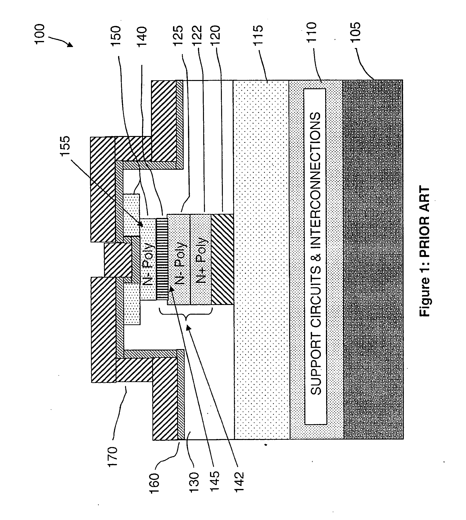
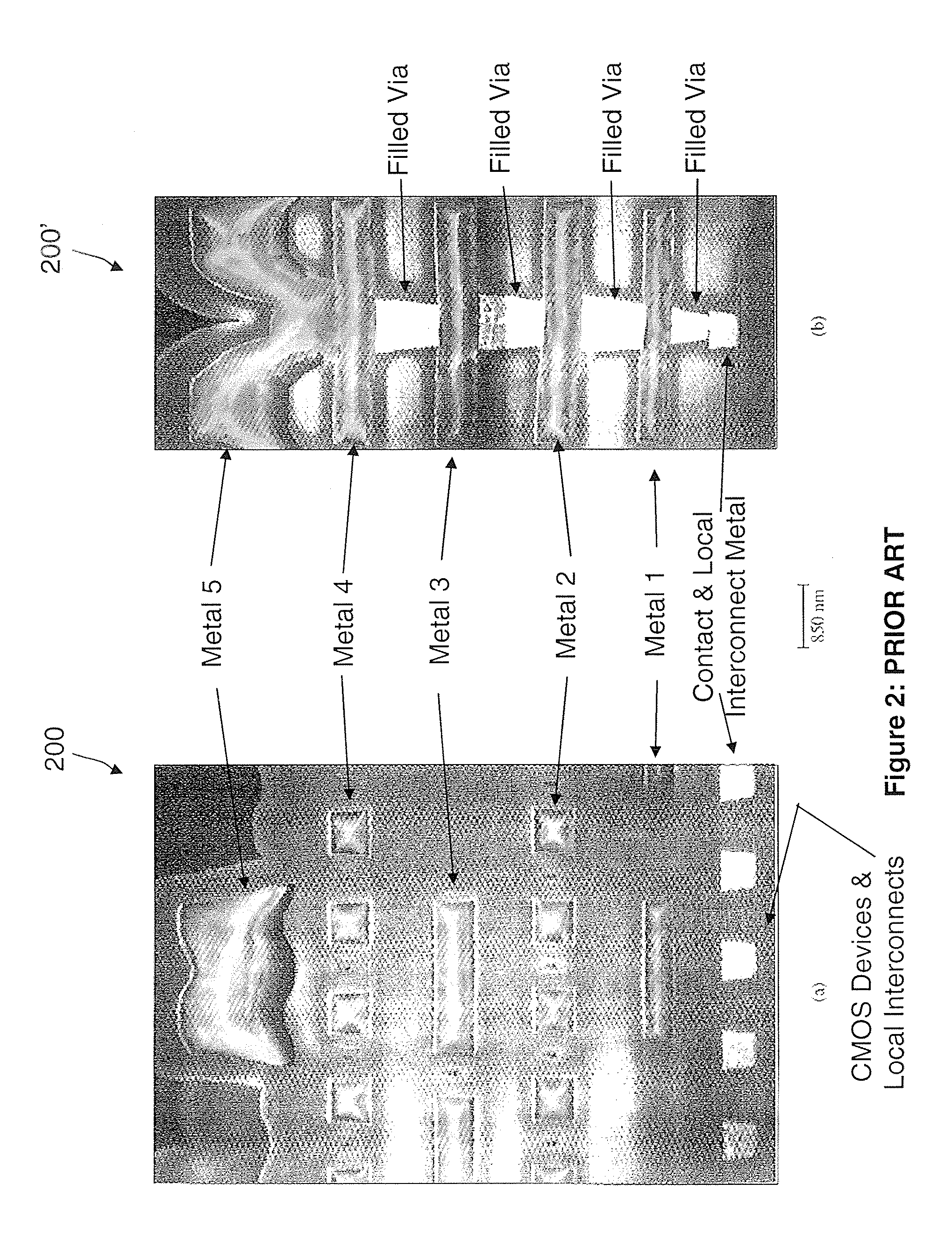
The technical problem addressed in this patent is how to create a three-dimensional (3-D) EPMOR memory chip design without limiting its effectiveness due to limitations in processing methods during manufacturing. Prior art designs had limitations in terms of forming effective interconnections among different parts of the circuit, resulting in slow performance and high resistance.

Method used


Image

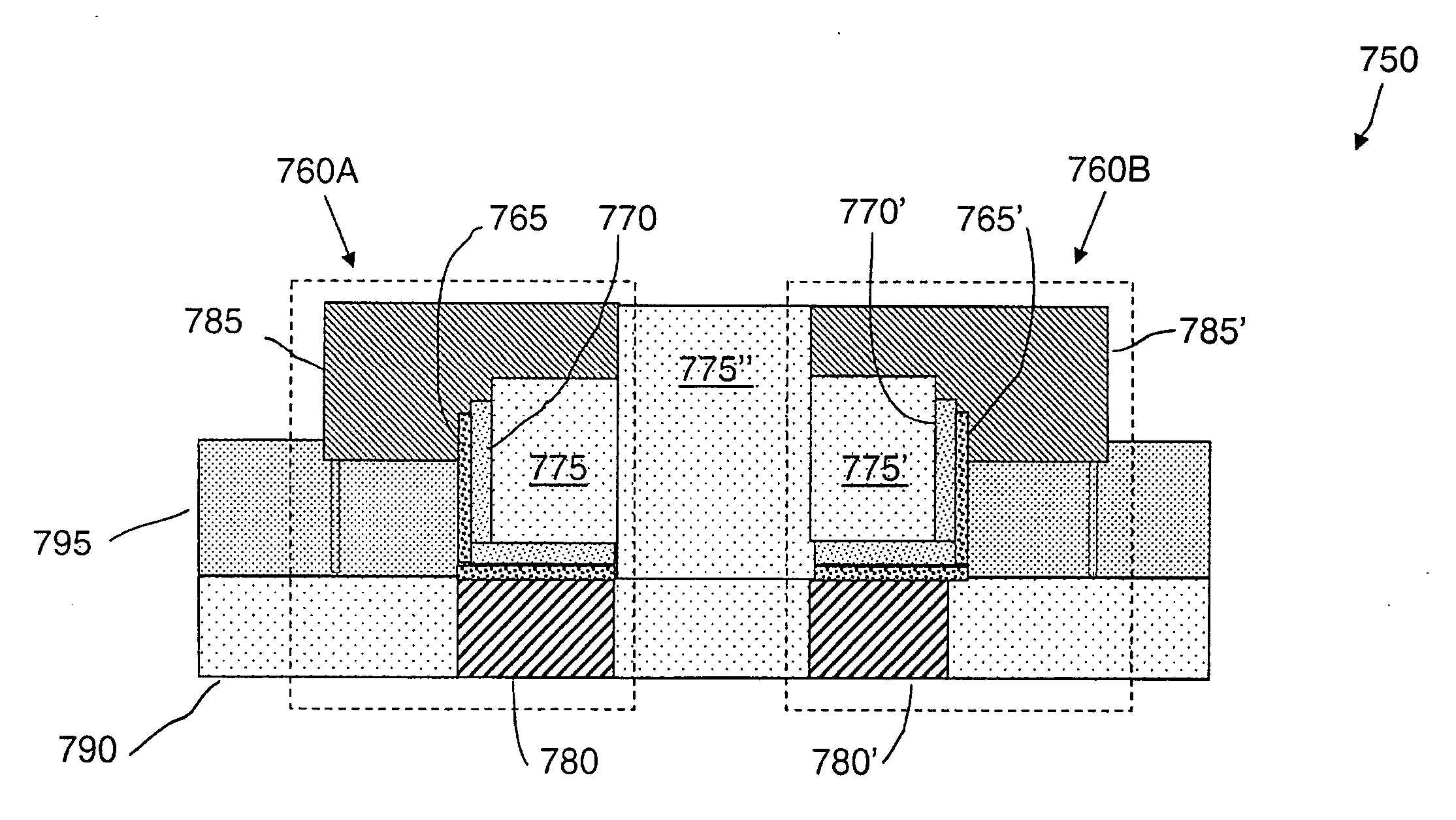
  • Nonvolatile nanotube diodes and nonvolatile nanotube blocks and systems using same and methods of making same
  • Nonvolatile nanotube diodes and nonvolatile nanotube blocks and systems using same and methods of making same
  • Nonvolatile nanotube diodes and nonvolatile nanotube blocks and systems using same and methods of making same

Examples


Embodiment Construction

[0171]Embodiments of the present invention provide nonvolatile diodes and nonvolatile nanotube blocks and systems using same and methods of making same.

[0172]Some embodiments of the present invention provide 3-D cell structures that enable dense nonvolatile memory arrays that include nanotube switches and diodes, can write logic 1 and 0 states for multiple cycles, and are integrated on a single semiconductor (or other) substrate. It should be noted that such nonvolatile memory arrays may also be configured as NAND and NOR arrays in PLA, FPGA, and PLD configurations for performing stand-alone and embedded logic functions as well.

[0173]Some embodiments of the present invention provide diode devices having nonvolatile behavior as a result of diodes combined with nonvolatile nanotube components, and methods of forming such devices.

[0174]Some embodiments of the present invention also provide nanotube-based nonvolatile random access memories that include nonvolatile nanotube diode device ...


PUM

PropertyMeasurementUnit
Thicknessaaaaaaaaaa
Thicknessaaaaaaaaaa
Electric potential / voltageaaaaaaaaaa

Abstract

A high-density memory array. A plurality of word lines and a plurality of bit lines are arranged to access a plurality of memory cells. Each memory cell includes a first conductive terminal and an article in physical and electrical contact with the first conductive terminal, the article comprising a plurality of nanoscopic particles. A second conductive terminal is in physical and electrical contact with the article. Select circuitry is arranged in electrical communication with a bit line of the plurality of bit lines and one of the first and second conductive terminals. The article has a physical dimension that defines a spacing between the first and second conductive terminals such that the nanotube article is interposed between the first and second conducive terminals. A logical state of each memory cell is selectable by activation only of the bit line and the word line connected to that memory cell.

Description


Claims


Application Information

Patent Timeline
Owner NANTERO
Why Eureka
Try Eureka