
Printing conductive patterns using LEP

a technology of conductive patterns and conductive patterns, which is applied in the direction of conductive pattern formation, conductors, instruments, etc., can solve the problems of reducing the performance of the fabricated device, losing the shape accuracy of the electronic device or integrated circuit being created, and expensive and slow processing

Active Publication Date: 2006-12-07
HEWLETT PACKARD DEV CO LP
View PDF12 Cites 3 Cited by
  • Summary
  • Abstract
  • Description
  • Claims
  • Application Information

AI Technical Summary

Benefits of technology

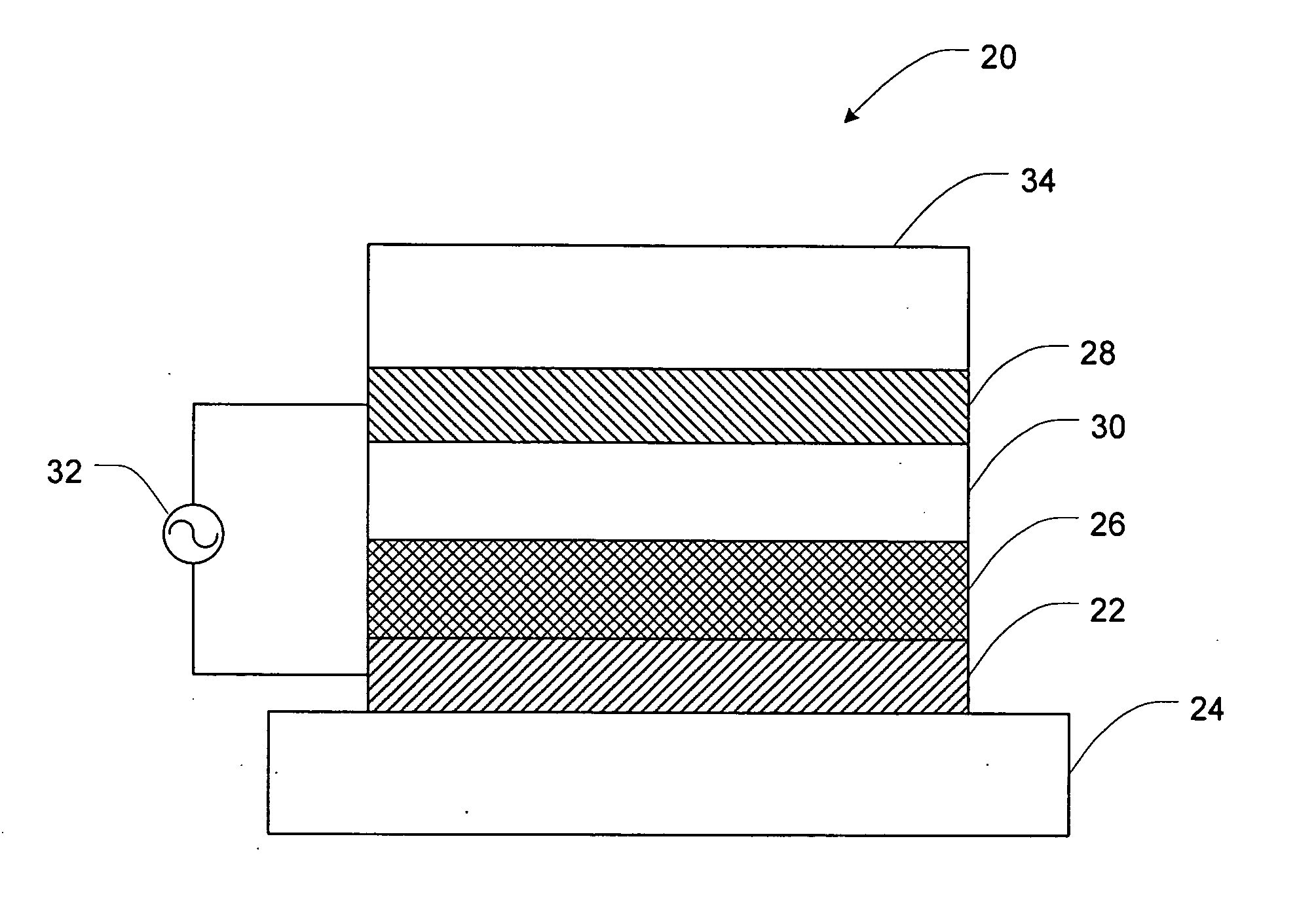
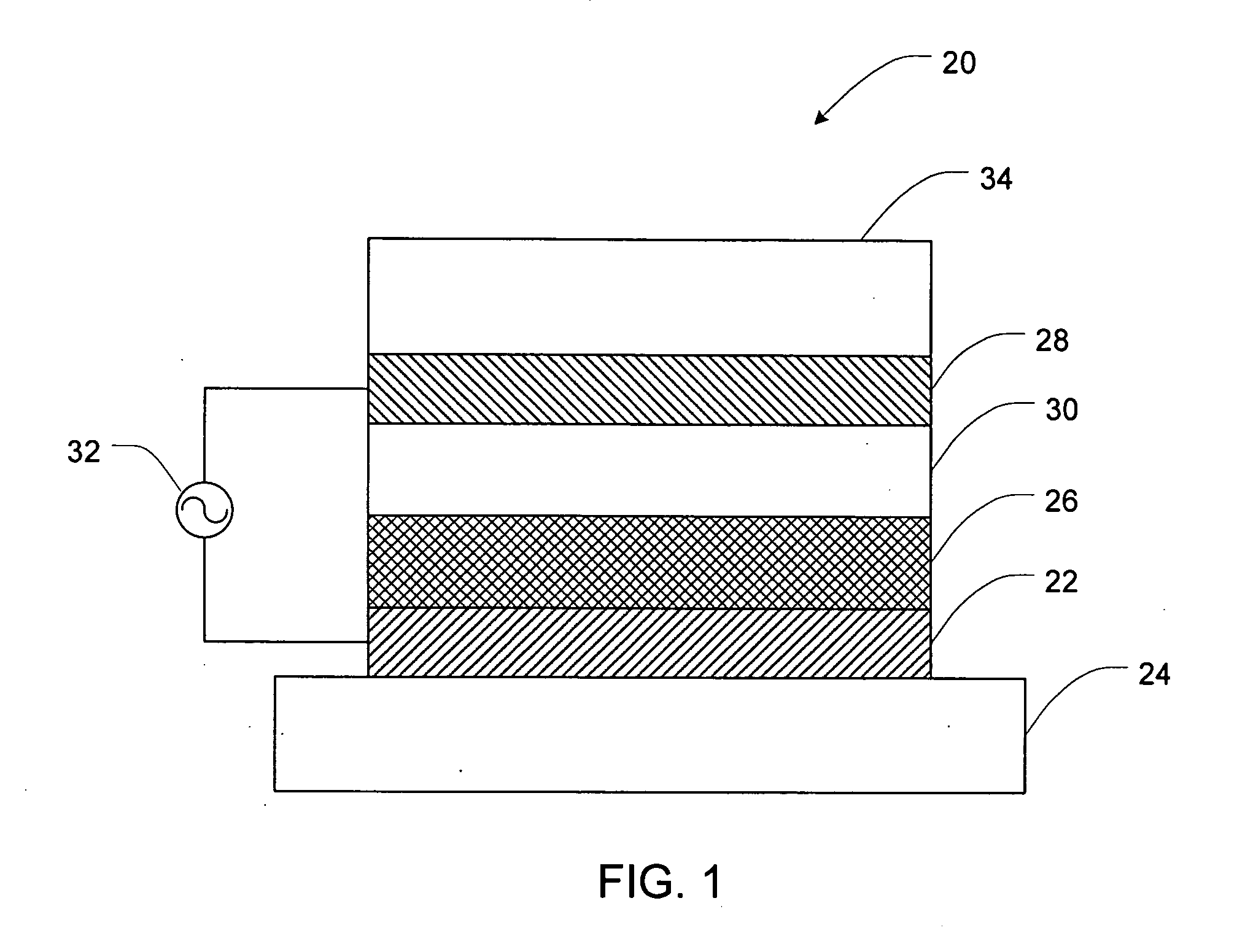
[0022] This problem has been solved in accordance with the present invention by printing certain organic polymers having at least two conductive states. For example, polymers having a state of relatively high electrical resistance can reliably be printed into electrostatic patterns using a LEP machine. Such polymers can be electrostatically printed directly onto a substrate, or they can be transferred to the substrate via one or more intermediate surfaces. In one aspect, the one or more intermediate surface can include a digital plate and / or a transfer medium such as an ITM. Because the polymers are printed in a relatively high resistance state, the laminar electric fields used to transfer the electrostatic patterns from one surface to another or from one surface to the substrate are not disturbed or interrupted to an extent which interferes with printing. In one embodiment, following transfer through the laminar electric field, the polymer can be altered to become more conductive, thus creating a conductive pattern.

Problems solved by technology

These processes are often expensive and slow.
In addition, processes such as dopant diffusion and etching are difficult to accurately control, and thus can lead to a loss in accuracy of the shape of the electronic device or integrated circuit being created.
These inaccuracies often lead to reduced performance of the fabricated device.

Method used


Image

  • Printing conductive patterns using LEP
  • Printing conductive patterns using LEP
  • Printing conductive patterns using LEP

Examples


example 1

[0041] Emeraldine base based ElectroInk is made as follows: 30-50 wt % by solids of emeraldine base is mixed with resin F varnish. Resin F varnish is a copolymer of polyacrylic acid and polyethylene. The two components are ground in S-0 atritor (made by Union process, Akron, Ohio USA) for about 4 hours in 19 wt % non volatile solid (NVS). The resulting slurry is diluted to 2 wt %. A solution of 5 wt % aluminum di / tri butoxide (ALB) is added to give 0.5 wt % of ALB by solids. The diluted slurry mixture is mixed for approximately 5 minutes. A 0.3 wt % amount of NCD (charge director) is added to give 50-70 pMoh (Moh=1 / Ohm) low field conductivity. The particle conductivity of the resulting emeraldine base ink can be measured to be in the range of 150-200 pMoh.

example 2

[0042] A conductive pattern can be created as follows: The 2 wt % emeraldine base ink is printed in a pattern on a paper substrate using an LEP process. In this case an Ultra-Stream LEP printer can be used. The pattern is allowed to dry in air and later heat fused on a hot plate to give an insulating pattern. The insulating pattern is covered with a 10 wt % solution of sulfuric acid for 5 minutes. The product of the emeraldine base and the sulfuric acid results in an emeraldine salt. The acid solution is wiped off the substrate. The print resolution is about 100 μm. The conductivity of the pattern can be measured to be about 15 kΩ by two probe measurement.

example 3

[0043] A conductive additive can be included as follows: A carrier resin (varnish) of 40 wt % NVS is ground with the combination of carbon black (Vulcan XC72) and the formulation of emeraldine base from Example 1 to total 60 wt % NVS. The resultant formulation is printed with a LEP process onto paper to give films with different conductivities based on the amount of carbon black in the formulation. The conductivity of the conductive pattern increases as the % carbon black in the formulation is increased.


PUM

PropertyMeasurementUnit
resistanceaaaaaaaaaa
wt %aaaaaaaaaa

Abstract

A method of printing an electrode component is disclosed. The method can include steps of electrostatically printing a polymer onto a substrate, where at least a portion of the printing occurs while the polymer is in a first conductive state, and altering the polymer to a second conductive state that is more conductive than the first conductive state, thereby forming the electronic component.

Description

FIELD OF THE INVENTION [0001] The present invention relates generally to the printing of electronic components. More particularly, the present invention relates to using liquid electro printing (LEP) to create electronic components. BACKGROUND OF THE INVENTION [0002] Electronics have become increasingly important in the everyday lives of many people in all aspects of society, including business, school, and home environments. As the need and desire for electronics increases, methods for low cost design and manufacturing of the electronic circuits that make up these devices become increasingly important. [0003] Numerous conventional techniques exist to construct electronic circuitry. Such processes can include photolithography, chemical vapor deposition, etching, masking, oxidation, dopant diffusion, etc. These processes are often expensive and slow. In addition, processes such as dopant diffusion and etching are difficult to accurately control, and thus can lead to a loss in accurac...

Claims


Application Information

Patent Timeline
Patent Type & Authority Applications(United States)
IPC IPC(8): H01L29/08
CPCH01B1/127H01B1/128H01L51/0022H05K3/105H05K2203/0517H05K3/1266H05K3/207H05K2201/0329H05K3/12G03G15/10G03G15/224G03G15/6585G03G15/6591H10K71/611
Inventor GRINWALD, YARONSPECTOR, TOMERGALIL, BOAZBACHAR, EYAL
Owner HEWLETT PACKARD DEV CO LP
Learn More