Vehicle Suspension System with a Variable Camber System

a suspension system and variable camber technology, applied in the direction of suspension arms, vehicle components, resilient suspensions, etc., can solve the problems of reducing vehicle directional stability, reducing tire life and fuel economy, and reducing vehicle body roll, so as to eliminate undesirable camber and toe changes, eliminate unnecessary tire scrubber, and optimal tire contact

Inactive Publication Date: 2009-08-06
BOSTON ROY
View PDF28 Cites 38 Cited by
  • Summary
  • Abstract
  • Description
  • Claims
  • Application Information

AI Technical Summary

Benefits of technology

[0015]The increased negative camber on the outer wheel counteracts the centrifugal force operating on the outer wheel while in a turn and optimizes the tire contact patch on the road surface. When the vehicle body rolls in a turn, the downward slope of the upper A-arm provides additional negative camber change in the same manner as a conventional unequal-length A-arm suspension.
[0016]A further aspect of the invention is that the vehicle may incorporate a variable ride height system and the present invention eliminates any undesirable camber and toe changes caused by ride height adjustments.
[0017]The present invention enables optimal tire contact with the road and eliminates unnecessary tire scrub. It also improves stability, traction, fuel economy, and cornering performance. The present invention also provides increase of vehicle responsiveness to steering inputs because the necessary camber changes to the outside steered wheel is provided directly as a part of the operator's steering input, instead of being solely derived from body roll as in a conventional unequal length a-arm suspension design. Transient vehicle weight shifts between straight ahead and turning operations will thus be anticipated and better managed through necessary wheel camber changes. Steering response will be improved and vehicle stability will be enhanced and optimized.

Problems solved by technology

When a vehicle is steered, the centrifugal forces cause the vehicle's body to roll.
These actions decrease vehicle directional stability and increase tire scrub that both reduces tire life and fuel economy.

Method used


Image

  • Vehicle Suspension System with a Variable Camber System
  • Vehicle Suspension System with a Variable Camber System
  • Vehicle Suspension System with a Variable Camber System

Examples


Embodiment Construction

[0034]While this invention is susceptible of embodiment in many different forms, there are shown in the drawings, and will be described herein in detail, specific embodiments of the invention with the understanding that the present disclosure is to be considered as an exemplification of the principles of the invention and is not intended to limit the invention to the specific embodiments illustrated.

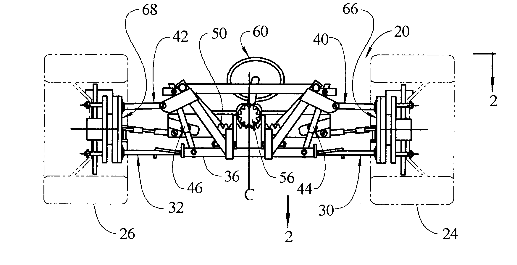
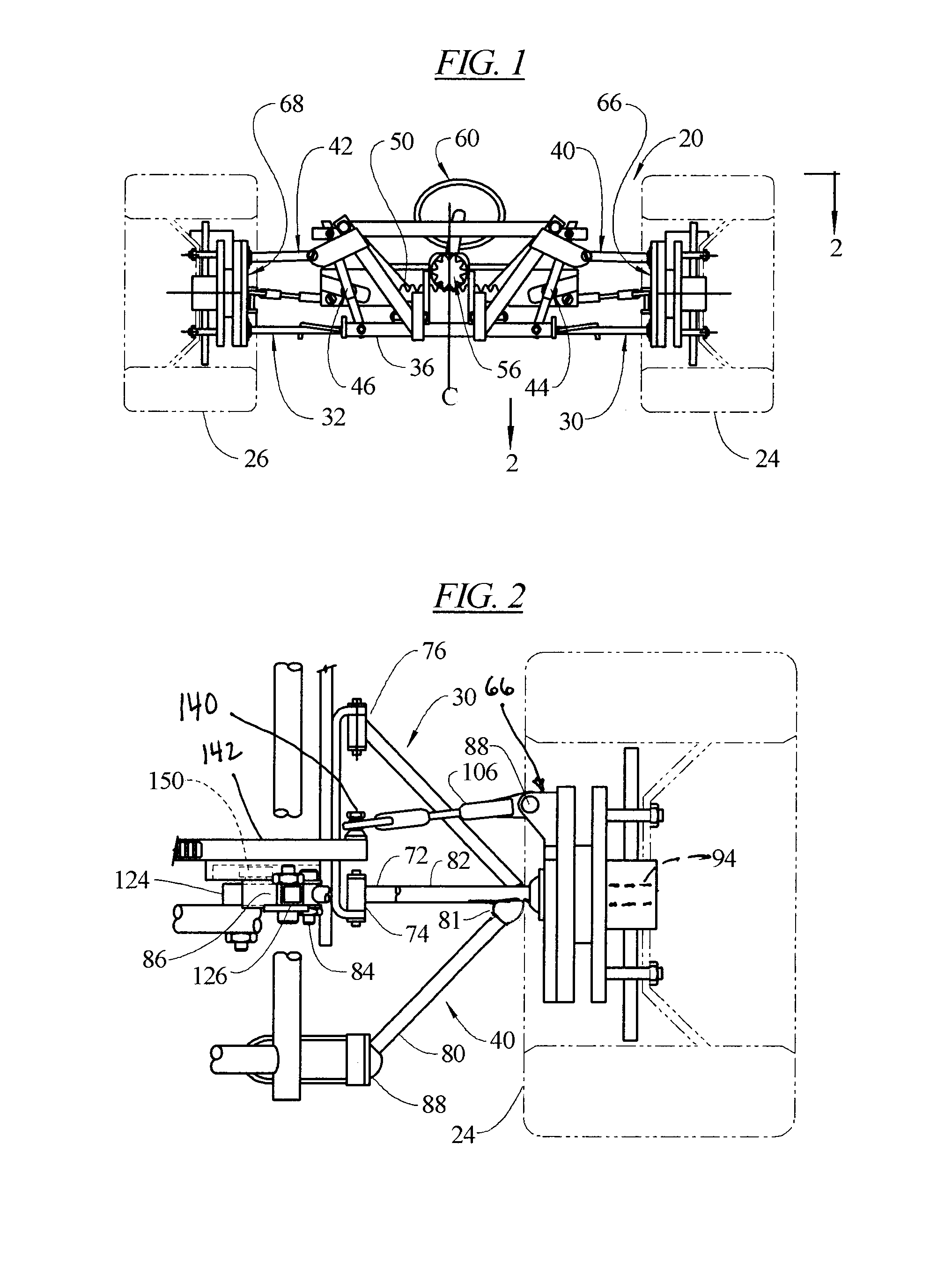
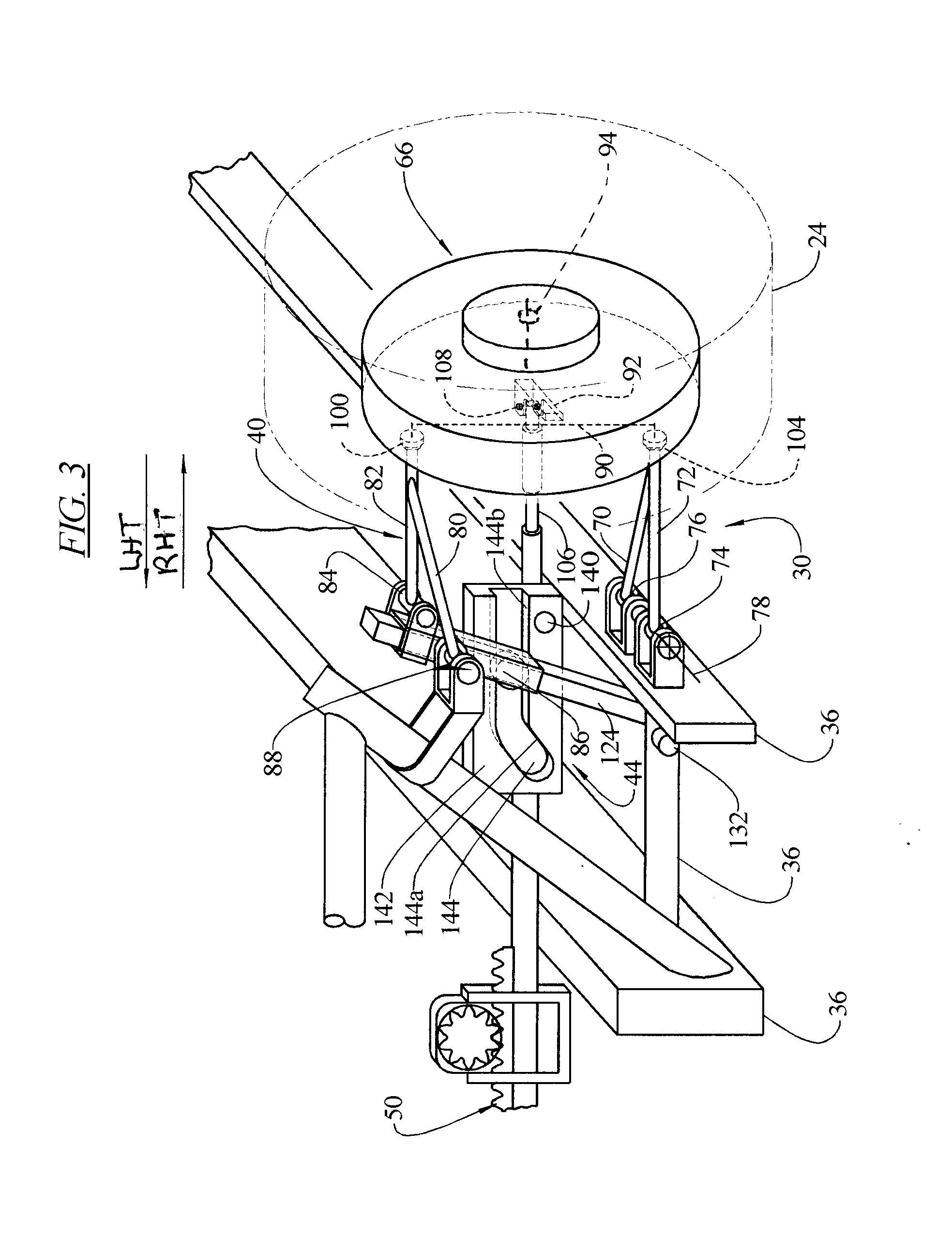
[0035]FIG. 1 illustrates an automobile suspension and steering system 20 according to the invention, viewing the vehicle in the forward oncoming direction. The system includes: front wheels 24, 26 (including tires), lower A-arms 30, 32 connected to a vehicle frame or chassis 36, upper A-arms 40, 42 connected to the frame 36 and to camber adjustment mechanisms 44, 46, and a steering rack 50 driven by a steering gear arrangement 56 that is controlled by a steering wheel. The upper A-arm 40 is connected to the lower A-arm 30 by a hub carrier 66 that also mounts the wheel 24. The upper A-arm...


PUM


Abstract

A suspension system for a vehicle provides a camber adjusting system that during a turn, lowers and draws inward the upper A-arm, or draws inward a strut head, which supports the outer front wheel, thereby providing more negative camber to that wheel in dynamic optimal proportion to the degree of the turn. The suspension system can be configured to remain at zero camber on the inner front wheel during the turn or can be configured to raise and move outward the upper A-arm, or move outward a strut head, which supports the inner front wheel, thereby providing more positive camber to that wheel in dynamic optimal proportion to the degree of turn.

Description

[0001]This application claims priority of U.S. Provisional Application Ser. No. 61 / 025,199 filed Jan. 31, 2008.TECHNICAL FIELD OF THE INVENTION [0002]This invention relates to the suspension systems of land vehicles. Specifically the invention relates to the dynamic adjustment of wheel camber within a suspension system of a vehicle.BACKGROUND OF THE INVENTION [0003]Vehicle suspension systems must adapt from static conditions of the vehicle at rest to dynamic conditions imposed by travel on a road surface, such as road slope, pitch and turns, external forces like wind gusts, vehicle speed, and load shifts. To handle such conditions, many vehicles have pre-set, fixed suspension parameters for toe, caster, and camber.[0004]The plane of a wheel is the plane perpendicular to the rotation axis of the wheel, passing through the center of the ground contact area of a tire. The term “camber” means the angle formed by the wheel plane relative to a line perpendicular to the ground. Camber of a...

Claims


Application Information

Patent Timeline
Patent Type & Authority Applications(United States)
IPC IPC(8): B60G7/00
CPCB60G3/20B60G2200/144B62D9/04B60G2204/421B60G2204/62B60G2200/46
Inventor BOSTON, ROY
Owner BOSTON ROY
Why Eureka
Try Eureka