
Hemodialysis apparatus

a hemodialysis apparatus and a technology of hemodialysis, applied in the direction of chemistry apparatus and processes, multi-stage water/sewage treatment, separation process, etc., can solve the problems of imbalance of electrolytes in the body, accumulation of blood, water and waste products, etc., to improve the efficiency of hemodialysis, simplify and miniaturize the hemodialysis apparatus, and maximize the effect of water exchang

Inactive Publication Date: 2016-05-19
HUMAN BIOMED INC
View PDF4 Cites 1 Cited by
  • Summary
  • Abstract
  • Description
  • Claims
  • Application Information

AI Technical Summary

Benefits of technology

The present invention is a hemodialysis apparatus that improves efficiency by alternating pressure between blood and dialysate to maximize water exchange. It also simplifies and miniaturizes the apparatus by eliminating the need for a blood pump. The apparatus includes a dialysate supply pump and discharge pump with a tube pressurizing member, a supporting wall, and a one-way valve to prevent dialysate from flowing backward. The apparatus repeats an expansion phase and a compression phase to filter blood through the dialyzer and store dialysate. The technical effects of the invention include increased efficiency, simplification, and reduction of costs for hemodialysis.

Problems solved by technology

When there is a kidney dysfunction, water and waste products that have to be discharged out of body accumulate in blood and imbalance of electrolytes in the body occurs.
However, there is a big hurdle in the effort to improve dialysis efficiency by the convective mass transfer, because hemodialyzers in typical hemodialysis apparatuses are limited in size and blood flow rate is restrictively allowed to be increased in consideration of the weight and blood vessel condition of a patient.

Method used


Image

  • Hemodialysis apparatus
  • Hemodialysis apparatus
  • Hemodialysis apparatus

Examples


first embodiment

[0048]Hereinafter, a hemodialysis apparatus according to the present invention will be described in detail with reference to the accompanying drawings.

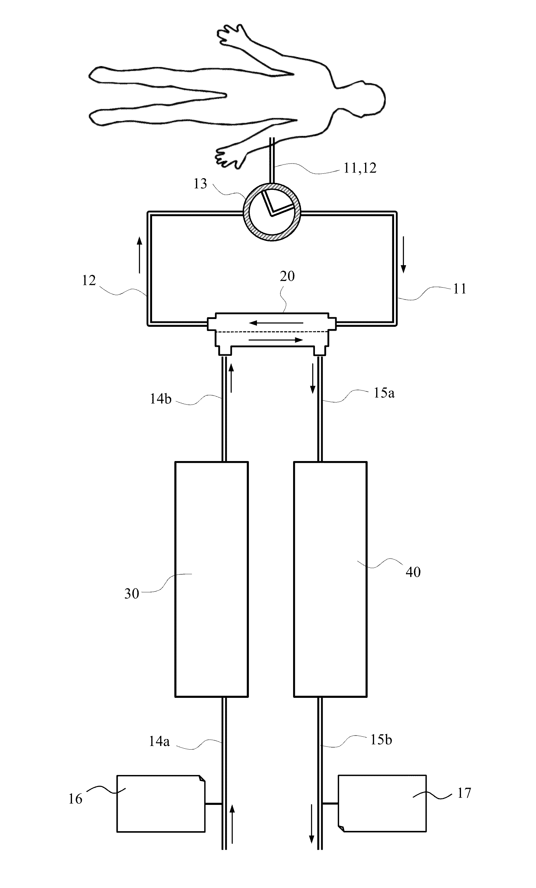
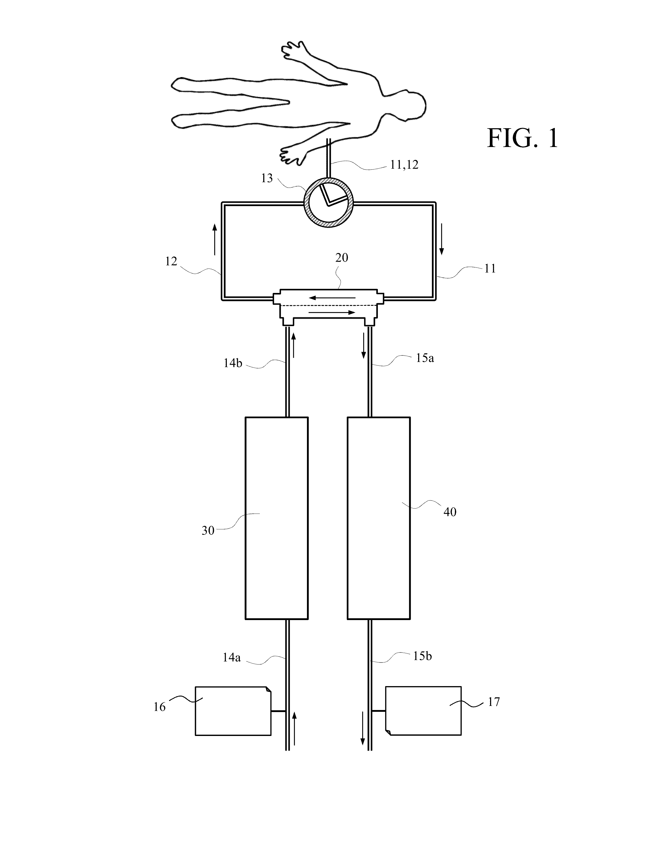
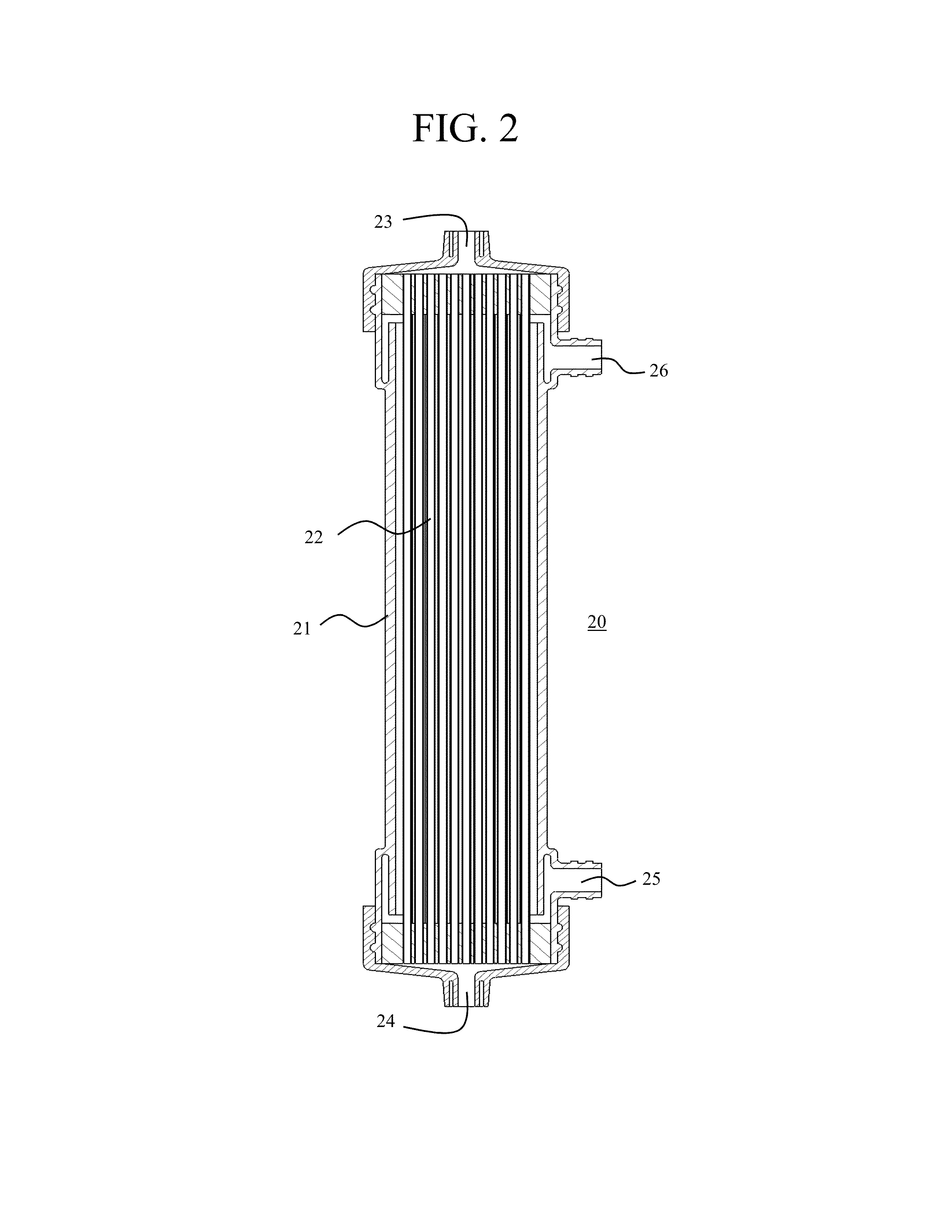
[0049]As shown in FIG. 1, a hemodialysis apparatus 10 includes a hemodialyzer 20 in which mass transfer occurs between blood and dialysate, a first blood tube 11 connecting a patient and the hemodialyzer 20 and allowing blood of a patient to be supplied to the hemodialyzer, a second blood tube 12 connecting the hemodialyzer 20 and a patient and allowing blood having passed through the hemodialyzer to be returned to a patient, a blood flow controller 13 controlling a blood flow passage through the first and second blood tubes 11 and 12, a dialysate supply pump 30 supplying dialysate to the hemodialyzer 20, and a dialysate discharge pump 40 discharging dialysate having passed the hemodialyzer.

[0050]A dialysate tube in which dialysate flows includes a dialysate supply tube 14 through which dialysate is supplied to the hemodialyzer 20 and...

second embodiment

[0071]Hereinafter, a hemodialysis apparatus 10 according to the present invention and an operation thereof will be described in detail with reference to the accompanying drawings.

[0072]As shown in FIG. 19, a hemodialysis apparatus 10 according to a second embodiment of the present invention includes the hemodialyzer 20 in which a mass transfer occurs between blood and dialysate, the first blood tube 11 supplying blood of a patient to the hemodialyzer 20, the second blood tube 12 returning blood of the hemodialyzer to a patient, a flow control device 50 controlling blood and dialysate flow passage through the blood tube 11 or 12 and the dialysate tube 14a, 14b, 15a or 15b, a dialysate supply pump 30 supplying dialysate to the hemodialyzer 20, and a dialysate discharge pump 40 discharging dialysate having passed the hemodialyzer.

[0073]FIG. 20 illustrates the dialysate supply pump 30 and the dialysate discharge pump 40 according to a second embodiment of the present invention. The dial...


PUM

PropertyMeasurementUnit
massaaaaaaaaaa
volumeaaaaaaaaaa
flow rateaaaaaaaaaa

Abstract

Provided is a hemodialysis apparatus including a hemodialyzer in which mass transfer occurs between blood and dialysate, a blood tube connecting the hemodialyzer and a patient to allow blood to flow therethrough, a blood flow controller which controls the blood flow passage through the blood tube, a dialysate supply pump supplying dialysate to the hemodialyzer, and a dialysate discharge pump discharging dialysate having passed through the hemodialyzer. The dialysate supply pump and the dialysate discharge pump further include a tube pressurizing member and a one-way valve or a roller and a roller driver. The blood tube includes a first blood tube in which blood of a patient is supplied to the hemodialyzer and a second blood tube in which blood passing through the hemodialyzer is returned to the patient.

Description

CROSS-REFERENCE TO RELATED APPLICATIONS[0001]Pursuant to 35 U.S.C. §119, this application claims the benefit of priority to Korean Patent Application No. 10-2014-0160448 filed Nov. 18, 2014, Korean Patent Application No. 10-2014-0160449 filed Nov. 18, 2014, and Korean Patent Application No. 10-2014-0164875 filed Nov. 25, 2014 in the Korean Intellectual Property Office, the entire contents of which are hereby incorporated by reference in their entirety.BACKGROUND[0002]The present invention relates to a hemodialysis apparatus configured to improve water exchange and mass transfer between blood and dialysate by quickly changing the dialysate pressure in a hemodialyzer using a pulsatile dialysate flow.[0003]When there is a kidney dysfunction, water and waste products that have to be discharged out of body accumulate in blood and imbalance of electrolytes in the body occurs. Most commonly performed to improve such a kidney failure symptom, is hemodialysis which is to circulate blood out ...

Claims


Application Information

Patent Timeline
Patent Type & Authority Applications(United States)
IPC IPC(8): A61M1/16A61M39/24
CPCA61M1/1601A61M39/24A61M1/1654A61M1/1639A61M1/1641A61M60/113A61M60/279A61M60/284A61M1/267
Inventor CHO, TAEBEOM
Owner HUMAN BIOMED INC
Learn More