
Ceiling-Mounted Troffer-Type Light Fixture

a ceiling-mounted light fixture and troffer-type technology, which is applied in the field of interior luminaires, can solve the problems of inability to adapt to installation and maintenance by a single individual, lack of prior ceiling-mounted lighting fixtures, and large amount of labor and time consumption, and achieve the effect of convenient installation, closure and removal

Inactive Publication Date: 2009-08-06
KENALL MFG
View PDF4 Cites 71 Cited by
  • Summary
  • Abstract
  • Description
  • Claims
  • Application Information

AI Technical Summary

Benefits of technology

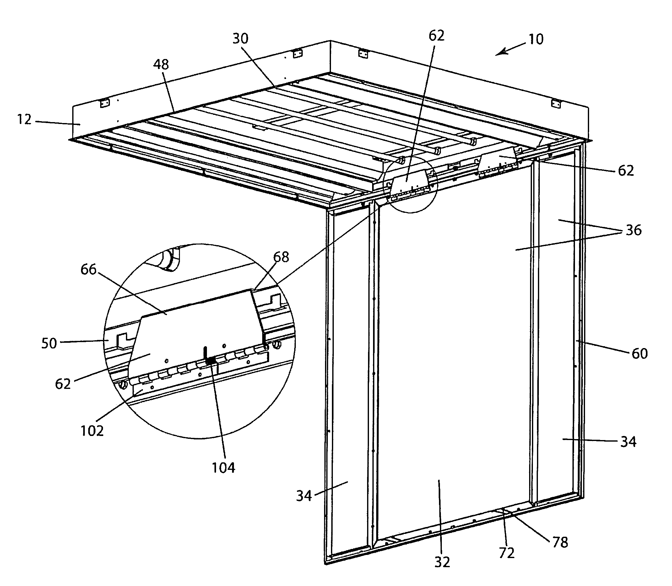
[0008]Another object is to provide a ceiling-mounted troffer-type light fixture with a large door which can be easily attached, closed and removed by a single individual.
[0015]6. The method of claim 5 wherein the removing comprises the steps of: (1) removing the lens screws which hold the cover against the body and allowing the cover to hang in a suspended position and move to a position in which it is suspended below the body by the catch arm(s) and the suspension member(s); (2) releasing the suspension member(s) from the suspension-member receiving opening(s); (3) rotating the cover about the rotatable engagement of the catch arm(s) with the first edge of the frame until the suspension member(s) disengage with the suspension-member-receiving opening(s), thereby enabling the fixture to hang in an open position; (4) lifting the fixture cover sufficiently to disengage the catch arm hook(s) from the hook-receiving opening(s); and (5) moving the cover to a position away from the body so as to facilitate fixture maintenance.

Problems solved by technology

In particular, conventional troffer-type light fixtures and lighting methods are not adapted for installation and maintenance by a single individual.
Specifically, if the door on a lighting fixture is large in size, installing, changing the door, or accessing the lamps often requires two or three maintenance people to remove the door and handle it.
This requires a substantial amount of labor and is time-consuming.
In summary, there are a number of problems and shortcomings in prior ceiling-mounted lighting fixtures.

Method used


Image

  • Ceiling-Mounted Troffer-Type Light Fixture
  • Ceiling-Mounted Troffer-Type Light Fixture
  • Ceiling-Mounted Troffer-Type Light Fixture

Examples


Embodiment Construction

[0031]In order to illustrate the inventive troffer-type fixture, a medical light fixture embodiment which includes a graphics-displaying light box middle section and two examination light side sections is used herein.

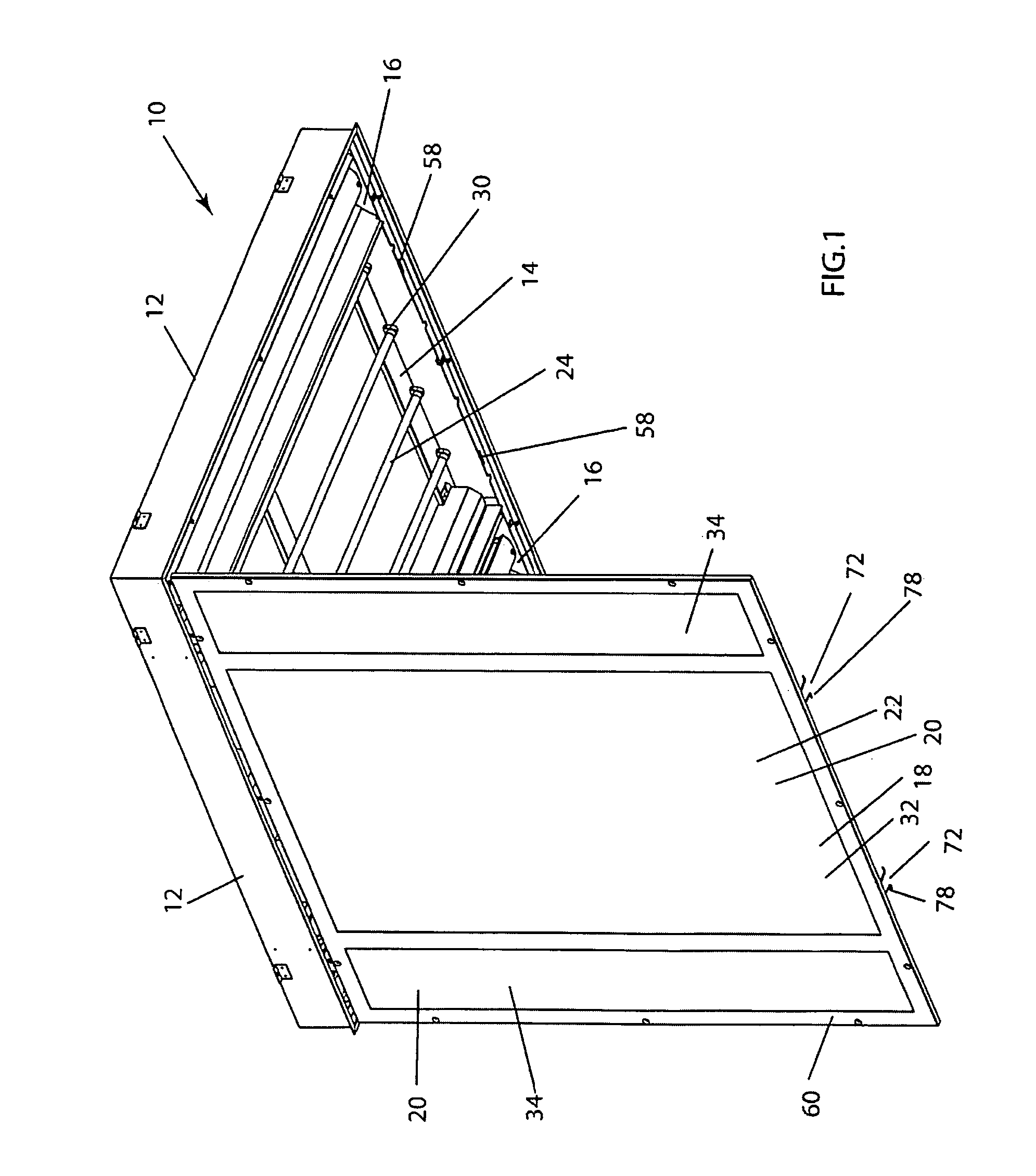
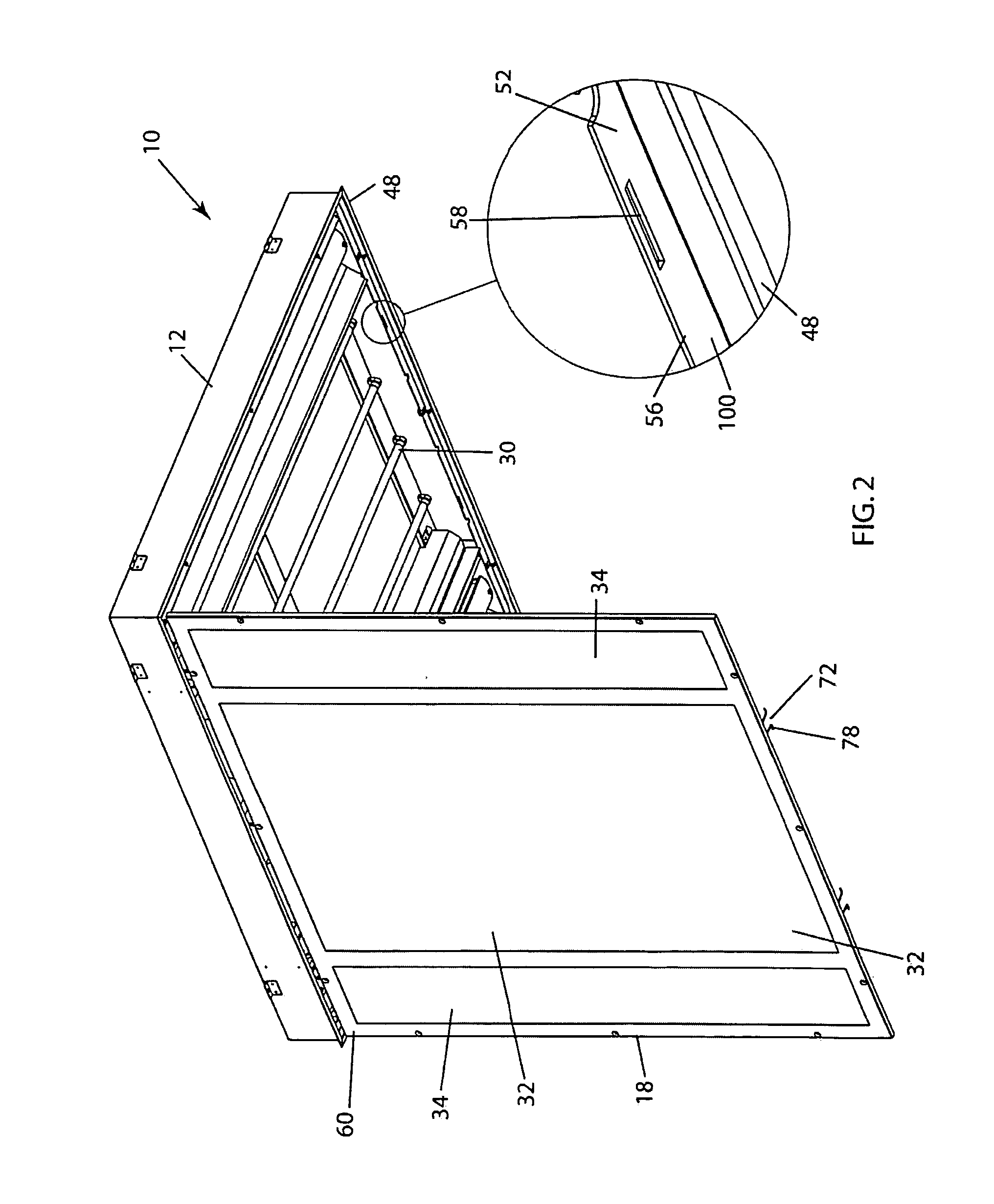
[0032]FIGS. 1-5 illustrate lighting fixture 10 having at least one exam-light 26 and a graphics image (not illustrated). As shown in FIG. 1, lighting fixture 10 has body 12 which has middle region 14 and two side regions 16 along opposite sides of middle region 14. As illustrated in FIGS. 1-3, lighting fixture 10 also has cover 18 moveably attached to body 12 which includes lens 20 over at least middle region 14. Lighting fixture 10 also includes a graphics image which is associated with middle region 14 and which is substantially parallel to lens 20. At least one graphics-light source 24 is within middle region 14 and is configured for illuminated display of the graphics image as shown in FIGS. 1-3. FIGS. 1-3 also illustrate lens 20 upon which graphics image 22 is illu...


PUM


Abstract

A ceiling-mounted troffer-type light fixture for illumination. The fixture comprises a body with a first flange having at least one hook-receiving opening and a second flange with a suspension-member-receiving opening. A cover includes a rectangular frame, at least one catch-arm and at least one suspension member. Frame fasteners along the frame engage the perimeter in a closed position. One-person attaching / closing and removal of the cover for maintenance is facilitated by the cover being supported in an open position, suspended position and fully engaged with the body in a closed position.

Description

FIELD OF THE INVENTION[0001]This invention is related generally to interior luminaires and more particularly to lighting fixtures which are ceiling-mounted and require periodic servicing.BACKGROUND OF THE INVENTION[0002]Many different types of lighting fixtures, including ceiling-mounted fixtures for various applications and locations, are known in the art. Such fixtures have been installed for illuminating stores, offices, supermarkets, schools, hospitals, banks, and other interior areas. Appreciating the versatility of such lighting fixtures, including the many engineering designs and configurations, there remains a need for a ceiling-mounted troffer-type light fixture whose cover can be attached, closed, removed and serviced by a single individual. In particular, conventional troffer-type light fixtures and lighting methods are not adapted for installation and maintenance by a single individual.[0003]Many ceiling-mounted fluorescent and LED luminaires require a fixture which is u...

Claims


Application Information

Patent Timeline
IPC IPC(8): F21S8/00
CPCF21S8/026F21V17/164F21W2131/208F21Y2103/00F21Y2105/001F21Y2101/02F21Y2113/00F21Y2105/10F21Y2115/10
Inventor HEIKING, NATHAN D.HAWKINS, JAMES W.
Owner KENALL MFG
Learn More