
Optical disc, optical disc manufacturing method, optical disc recording device and optical disc reproduction device

a technology of optical discs and recording devices, applied in the field of optical discs, optical disc manufacturing methods, optical disc recording devices and optical disc reproduction devices, can solve the problems of hindering the sound distribution of digital copyrighted works, a large number of illegal optical disc manufacturers, and the protection of the copyright of recorded digital content has become an essential technical problem, so as to prevent illegal duplication of optical discs

Active Publication Date: 2009-08-06
PANASONIC CORP
View PDF10 Cites 23 Cited by
  • Summary
  • Abstract
  • Description
  • Claims
  • Application Information

AI Technical Summary

Benefits of technology

[0023]In view of the above problems, an object of the present invention is to provide an optical disc, an optical disc manufacturing method, an optical disc recording device and an optical disc reproduction device capable of recording sub-information necessary to reproduce main information without deteriorating the reading accuracy of the main information, so that the illegal duplication of optical discs is prevented.
[0031]According to the present invention, the sub-information necessary to reproduce the main information can be recorded without deteriorating the reading accuracy of the main information, so that the illegal duplication of the optical disc can be prevented.

Problems solved by technology

Accordingly, as the optical disc capacity increases, the value of digital contents recorded on one optical disc increases and the protection of the copyright of the recorded digital content has become an essential technical problem.
However, nowadays, there are a great number of illegal optical disc manufacturer such as pirate makers for illegally duplicating digital contents from optical discs.
This hinders a sound distribution of digital copyrighted works and creates a situation where profits are not fairly distributed to copyright holders.
However, by any of these methods, it is difficult to record medium unique information of the optical disc while preventing the illegal duplication without increasing cost required for the manufacturing of the optical disc and without deteriorating the reading accuracy of main information.
It is also difficult to record the medium unique information of the optical disc while efficiently preventing illegal duplication without sacrificing the recording region for the main information.
However, in the case of a Blu-ray disc, accuracy in the order of several tens nanometers in a radial direction is necessary for positioning between these tracks, and it is difficult to record both the guide groove and the concave and convex marks using a normal mastering apparatus.
In order to realize this, a special mastering apparatus is necessary and an increase of cost required for the manufacturing of an optical disc is unavoidable.
Thus, it is necessary to search and save the mark or space with the specified length or longer, whereby a recording time for recording the sub-information is uselessly consumed and cost required for the manufacturing of the optical disc increases.
Therefore, in this case as well, the recording time or reproduction time is uselessly consumed.
Accordingly, the reading accuracy of the prerecorded first signal deteriorates and a recoverable defect margin such as an error correction deteriorates.

Method used


Image

  • Optical disc, optical disc manufacturing method, optical disc recording device and optical disc reproduction device
  • Optical disc, optical disc manufacturing method, optical disc recording device and optical disc reproduction device
  • Optical disc, optical disc manufacturing method, optical disc recording device and optical disc reproduction device

Examples


first embodiment

(1-1) Optical Disc According to First Embodiment

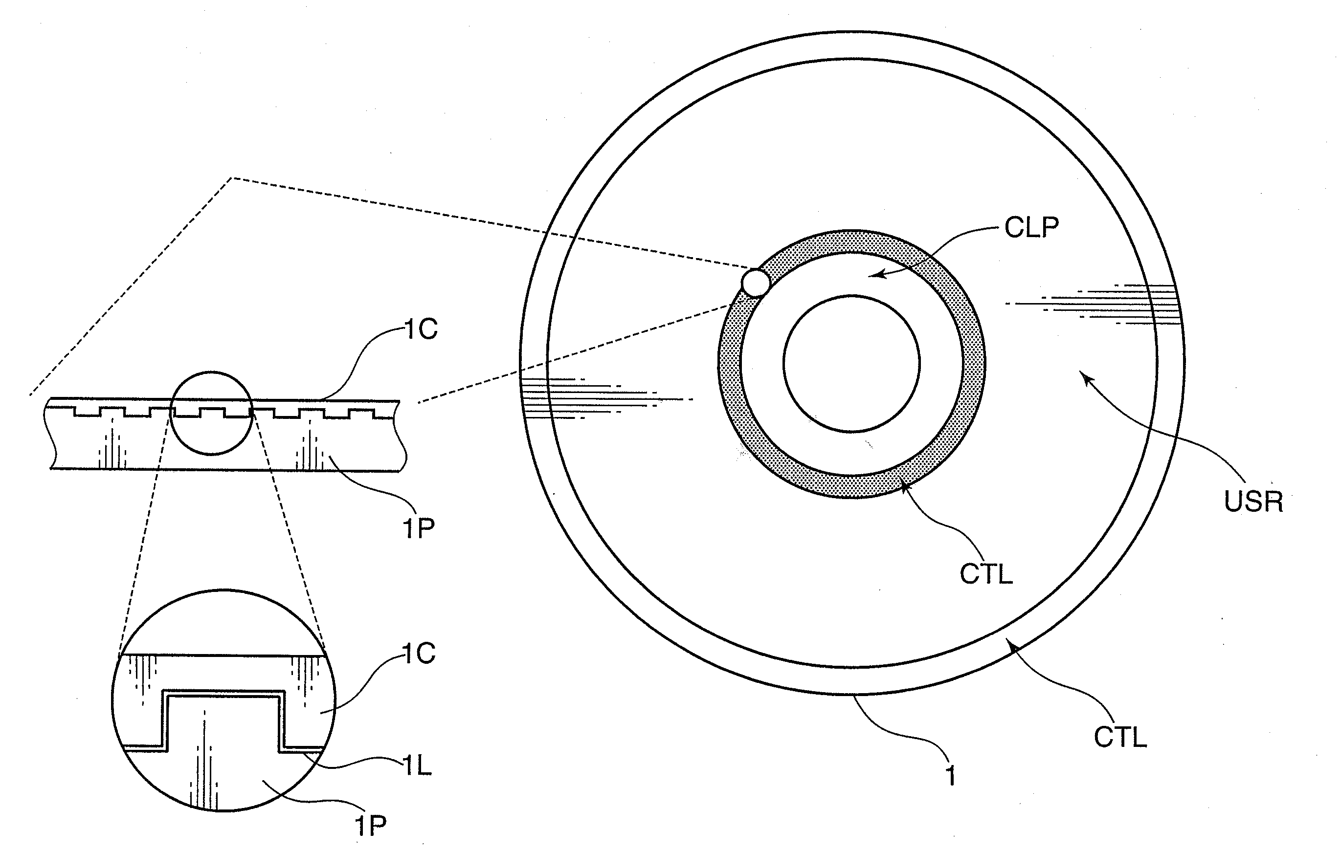
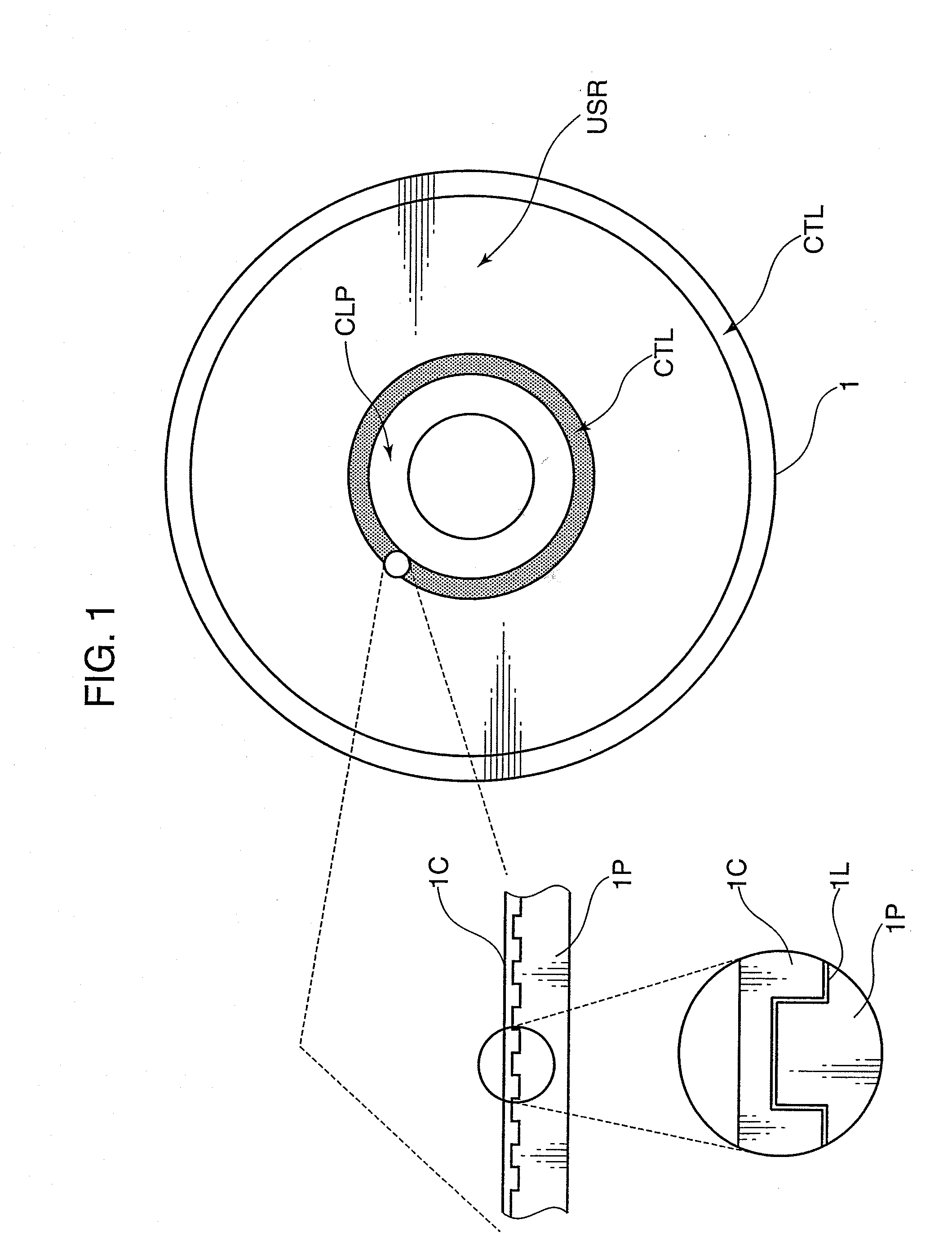
[0061]FIG. 1 is a conceptual diagram showing the construction of an optical disc 1 according to a first embodiment. The optical disc 1 shown in FIG. 1 is comprised of a clamp region CLP, control regions CTL at inner and outer circumferential sides, and a user region USR.

[0062]The clamp region CLP is a feed portion upon loading the optical disc 1 and, normally, no information is recorded thereon.

[0063]The control regions CTL are provided at two positions, i.e. at the inner and outer circumferential sides of the user region USR, and management information, copyright information, physical characteristic information or the like of the optical disc 1 is recorded by concave and convex recording marks. The characteristic of the optical disc 1 is that a medium ID (medium unique information) is recorded by locally changing the reflectivity of a reflective film 1L on the concave and convex marks on the same track as the one formed by the concave...

second embodiment

(2-1) Optical Disc According to Second Embodiment

[0182]FIG. 10 is a conceptual diagram showing the construction of an optical disc according to a second embodiment. The optical disc 1 shown in FIG. 10 includes a clamp region CLP to be clamped upon loading the optical disc 1 into an optical disc recording device or an optical disc reproduction device, two control regions CTL at inner and outer circumferential sides where information on copyright, a physical characteristic of the optical disc 1 or management information of the optical disc 1 is recorded in the form of concave and convex marks, and a user region USR where, for example, encrypted movie title or PC data information is recorded in the form of concave and convex marks.

[0183]At least the user region USR and the control regions CTL of the optical disc 1 are formed by transferring the concave and convex marks to an optical disc substrate 1P made of polycarbonate or the like, applying a reflective film 1L, whose reflectivity c...

third embodiment

(3-1) Optical Disc According to Third Embodiment

[0279]FIG. 19 is a conceptual diagram showing the construction of an optical disc according to a third embodiment. An optical disc 150 of the third embodiment includes a user region 151, on which content data is recorded, and a sub-information recording region 152, on which the identification information of the optical disc 150 is recorded.

[0280]Content data is recorded in the form of concave and convex marks beforehand in the user region 151, and neither concave and convex marks nor wobble guide grooves are recorded in the sub-information recording region 152. A reflective film of the optical disc 150 is a recording film whose reflectivity changes by the irradiation of laser light.

[0281]No special synchronization codes are included in the sub-information recording region 152 where the identification information of the optical disc 150 is recorded, and the identification information is recorded from the same angular position as that of...


PUM

PropertyMeasurementUnit
Volumeaaaaaaaaaa
Digital informationaaaaaaaaaa
Lengthaaaaaaaaaa

Abstract

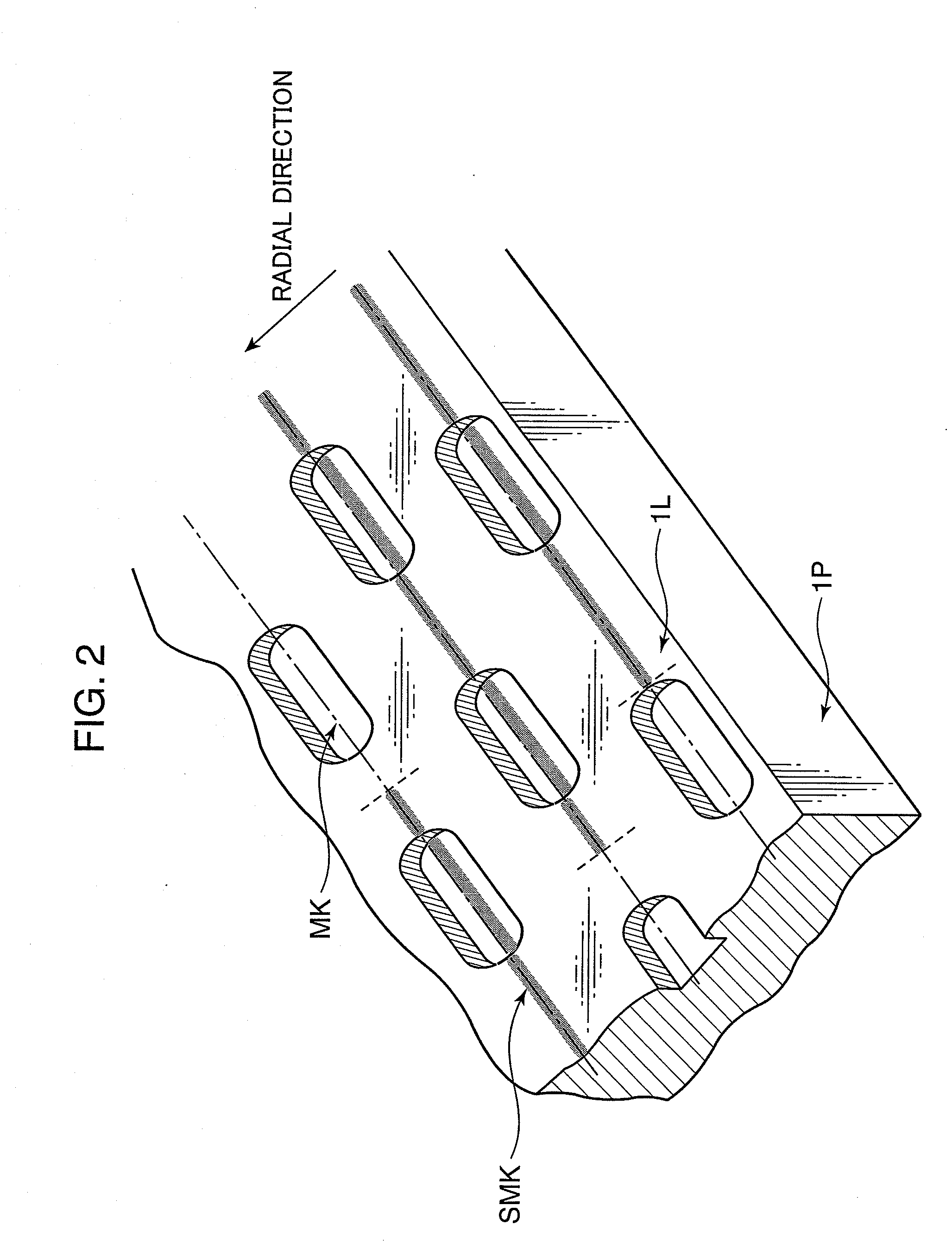
Sub-information necessary to reproduce main information is recorded without deteriorating the reading accuracy of the main information, so that the illegal duplication of an optical disc is prevented. An optical disc 1 is produced by forming a reflective film 1L on concave and convex marks MK after the concave and convex marks MK synchronized with the integral multiple of a channel bit length are formed in accordance with modulated main information. Thereafter, continuous or intermittent laser light synchronized with the integral multiple of the channel bit length is irradiated at intervals longer than the longest one of the concave and convex marks MK in accordance with a spiral track formed in a circumferential direction of the concave and convex marks MK, whereby an optical characteristic of the reflective film 1L is changed to form a recordable mark SMK and sub-information necessary to reproduce the main information is recorded in a superimposition manner.

Description

BACKGROUND OF THE INVENTION[0001]1. Field of the Invention[0002]The present invention relates to an optical disc such as a CD, a DVD or a Blu-ray disc, an optical disc manufacturing method for manufacturing an optical disc, an optical disc recording device for recording information on an optical disc and an optical disc reproduction device for reproducing information from an optical disc.[0003]2. Description of the Background Art[0004]Conventionally, optical discs are widely used as inexpensive recording media for digital information. For example, a Blu-ray disc has a capacity of 25 gigabytes with a single layer and 50 gigabytes with two layers and can record high-vision and good-quality video contents about 2 to 4.5 hours. Accordingly, as the optical disc capacity increases, the value of digital contents recorded on one optical disc increases and the protection of the copyright of the recorded digital content has become an essential technical problem.[0005]However, nowadays, there ...

Claims


Application Information

Patent Timeline
IPC IPC(8): G11B7/00G11B7/24B29C59/16G11B7/24094G11B7/24097
CPCG11B7/00736G11B7/24094G11B20/00086G11B2220/2541G11B20/00173G11B20/00586G11B20/1252G11B20/00115
Inventor YAMAOKA, MASARUSHOJI, MAMORUNISHIKIORI, KEIJIUSUI, MAKOTOMORIYA, MITSURO
Owner PANASONIC CORP
Learn More